


7 - 39
MDS-D2/DH2 Series Instruction Manual
7.3 Troubleshooting
7.3.4 Parameter Numbers during Initial Parameter Error
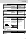
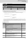
If an initial parameter error (alarm 37) or set parameter warning (warning E4) occurs, the axis name and the No. of the
error parameter that exceeds the setting range will appear on the NC Diagnosis screen as shown below:
S02 Initial parameter error ○○○○□
○○○○ : Error parameter No.
□ : Axis name
S52 Parameter error warning ○○○○□
○○○○ : Error parameter No.
□ : Axis name
If an error No. in the following table is displayed as the error parameter No. even when the parameter is set to a value
within the setting range, an error is occurring due to the hardware compatibility or specifications or in relation to several
other parameters. Check the specifications of the servo and spindle system and the descriptions in the following table to
correctly set the parameters.
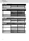
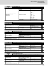
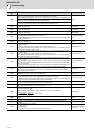
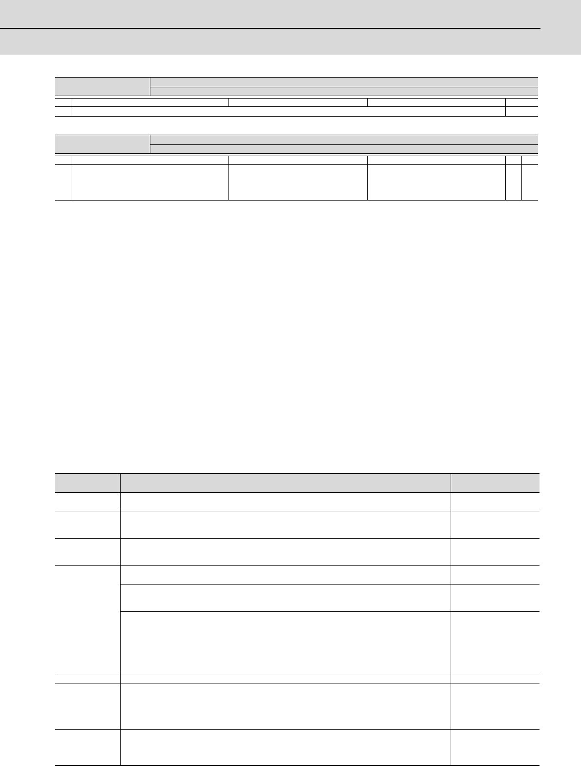
(1) Servo parameter error No.
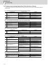
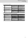
Warning No.
EE
Power supply: Fan stop warning
A cooling fan built in the power supply unit stopped.
Investigation details Investigation results Remedies CV
1 Check the alarm No. "72" items.
◯
Warning No.
EF
Power supply option unit warning:
A warning was detected in the power backup unit (an option unit for the power supply).
Investigation details Investigation results Remedies SV SP
1 Check the LED display on the power backup unit.
Check the LED display on the power backup
unit to identify what warning is occurring to
the unit.
Fix the error occurring to the power backup
unit and remove the warning.
Refer to "9.5.3 List of power backup function
warnings".
◯◯
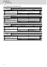
Error parameter
No.
Details Related parameters
2217
The motor selected is of a motor series different from the drive unit’s input voltage (200V/400V).
Or a motor of an incompatible motor series is selected.
SV017
2219
-In a semi-closed loop control system, the setting value of SV019 is different from that of SV020. Set them
to the same value.
-SV019 is set to a value outside the setting range.
SV019
2220
-The resolution of the motor side encoder actually connected is not consistent with the setting value for
SV020.
-SV020 is set to a value outside the setting range.
SV020
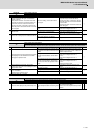
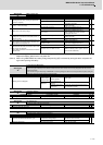
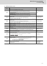
2225
Incompatible motor type is selected. The machine side encoder type or the motor side encoder type is
incorrectly set.
SV017, SV025
For the speed command synchronous control system with MDS-D2/DH2-V2/V3,
-The L axis for the drive unit is set as the secondary axis. Set the M axis as the secondary axis.
-The motor side encoders for the L axis and the M axis are different. Use encoders of the same specifications.
SV025
For the distance-coded reference scale system,
-When a HEIDENHAIN serial conversion interface unit is connected, the encoder type setting is different from
the connected unit type.
-When a HEIDENHAIN serial conversion interface unit with the rotary type is connected, the ball screw pitch
(SV018) is set to a value other than "360".
-The speed command synchronous control and the distance-coded reference scale connection are set
concurrently.
SV018, SV025, SV130
SV131
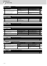
2228 The magnetic pole shift amount (SV028) is set for a general servo motor (not a built-in motor). SV028
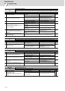
2233
The vertical axis pull up function (SV033/bitE) is set in the following conditions:
-when the vertical axis pull up direction is not set (SV032=0)
-when the drop prevention function is not set (SV048=0)
The vertical axis pull up function (SV033/bitE) is not set in the following condition:
-when the vertical axis pull up distance is set (SV095≠ 0)
SV032, SV033, SV048
SV095
2234
Parallel connection is set when the motor is not a linear servo motor.
Or the DC excitation mode (SV034/bit4) is set in the following conditions:
-when the NC is powered ON
-when a general servo motor (not a built-in motor) is used.
SV034