


6 - 18
6 Spindle Adjustment
MITSUBISHI CNC
6.1.5 Synchronous Tapping Adjustment
(1) Gain setting and time constant determination
[1] For speed loop gain during synchronous tapping, speed loop gain set 2, which consists of SP008 (speed loop
gain 2), SP009 (speed loop lead compensation 2), and SP010 (speed loop delay compensation 2), is used.
Thus, SP035 has to be set as follows. For position loop gain, set standard 33 to SP002 (position loop gain
interpolation mode).
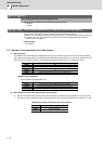
<List of parameters used for adjustment>
<Related servo parameters>
Set the spindle and interpolation axis by tapping.
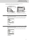
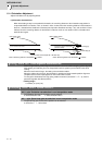
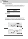
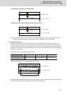
[2] Create a NC program so that the synchronous tapping operation program has 3000r/min of spindle rotation
speed, 1mm (equivalent of M6 screw) of screw pitch size, and depths at which the following two different
operation patterns are generated.
(Note that the operation conditions, such as spindle rotation speed and screw pitch, may be specified by the
machine manufacturer.)
Parameter Setting value
SP002 33
SP008
Value in SP005 set at "Gain Adjustment"
(Initial setting value: 150)
SP009 1900
SP010 0
SP035 0200: Speed loop gain set 2 selection (Validate bit9)
Parameter Setting value
SV049 Set the same value as spindle parameter "SP002"
SV050 Set it when using SHG control (when not using, set to "0" )
SV058 Set it when using SHG control (when not using, set to "0" )
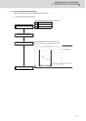
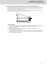
Operation pattern 1
A
djust depth so that motor rotation speed waveform shapes trapezoids
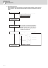
Operation pattern 2
A
djust depth so that motor rotation speed waveform shapes mountain-valley
Constant s
p
eed area
Spindle rotation speed (r/min)
Spindle rotation speed (r/min)
Time (sec)
No constant s
p
eed area
Spindle rotation speed (r/min)
Spindle rotation speed (r/min)
Time (sec)