


Appendix 1 - 18
Appendix 1 Cable and Connector Specifications
MITSUBISHI CNC
Appendix 1.4 Connector Outline Dimension Drawings
Appendix 1.4.1 Connector for Drive Unit
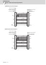
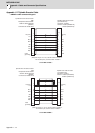
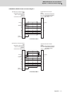
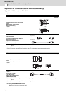
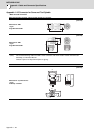
Optical communication cable connector
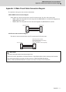
(Note 1) The POF fiber's light amount will drop depending on how the fibers are wound. So, try to avoid wiring the
fibers.
(Note 2) Do not wire the optical fiber cable to moving sections.
(Note 3) Contact: Japan Aviation Electronics Industry, Limited http://www.jae.com/jaehome.htm
(Note 1) The PCF fiber's light amount will drop depending on how the fibers are wound. So, try to avoid wiring the
fibers.
(Note 2) Do not wire the optical fiber cable to moving sections.
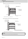
For wiring between NC and drive unit
Refer to the instruction manual for CNC.
Optical communication connector
For wiring between drive units (inside
panel)
Manufacturer: Japan Aviation
Electronics Industry
<Type>
Connector:2F-2D103
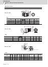
[Unit:mm]
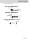
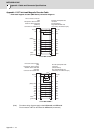
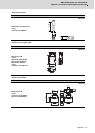
Cable appearance
<Type>
Connector: 2F-2D103 (Japan Aviation
Electronics Industry)
Optical fiber: ESKA Premium
(MITSUBISHI RAYON)
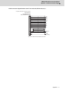
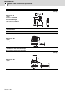
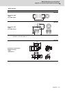
Optical communication connector
For wiring between drive units (outside
panel)
Manufacturer: Tyco Electronics
<Type>
Connector: 1123445-1
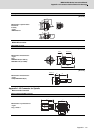
[Unit:mm]
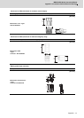
Cable appearance
<Type>
Connector: 1123445-1
(Tyco Electronics)
Optical fiber: ESKA Premium
(MITSUBISHI RAYON)
(13.4)
(15)
(6.7)
(
20.9
)
8
+0
37.65
(2.3)
(1.7)
㧔L҇0.1 㧕
㧔L҈0.2 㧕
m
m
22.7
8.5 20.3