


6 - 16
6 Spindle Adjustment
MITSUBISHI CNC
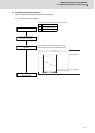
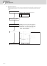
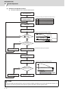
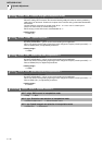
(3) Orientation time adjustment method
(a) Orientation adjustment from maximum rotation speed
POINT
Check the orientation operation with the maximum inertia by installing a workpiece or tool to the spindle head. However, if it
is dangerous to check the operation at the maximum speed, slow down to the safe speed to check.
CH1
CH2
CH3
YES
NO
Adjust orientation time
Rotate spindle at the maximum
rotation speed
Increase SP016 by +5
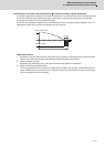
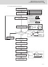
Current edge <
Current control value ?
YES
NO
NO
YES
Increase SP016 by +5
Command M19 (orientation stop)
Rotate spindle at the maximum
rotation speed
Command M19 (orientation stop)
Multiply SP016 setting value by 1/2
(Orientation stop time) -
(deceleration time) < 0.4s
Set to SP016 as recovery time constant.
Orientation time
adjustment completed
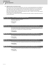
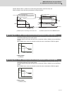
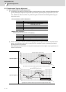
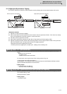
0
0
Current ed
g
e
[
1
]
Current limit range
at deceleration
(SP152 or SP184)
Time(s)
Current edge [2]
SP152
-(SP152)
Compen. amount
One rotation?
(Current edge?)
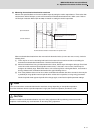
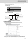
Orientation stop waveform example(1 rotation)
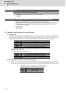
0
4.00s
deceleration time = 3.70s
Ch3:In-position signal
Stop within
In-position
Orientation time
= 4.00s-3.70s= 0.30s 0.4s OK
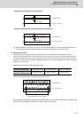
Orientation stop waveform example(1 rotation)
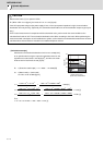
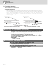
Set the "Time-series data
measurement" with NC Analyzer
as shown on the right
Get Waveform type
< NC Analyzer setting (Time-series data measurement) >
Speed feedback (r/min)
Current feedback
Control output 1(bitC) *In-position signal
Ch1:Speed feedback
Ch2:Current
feedback
Ch1:Speed feedback