


5 - 70
5 Servo Adjustment
MITSUBISHI CNC
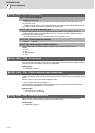
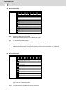
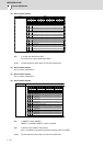
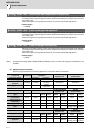
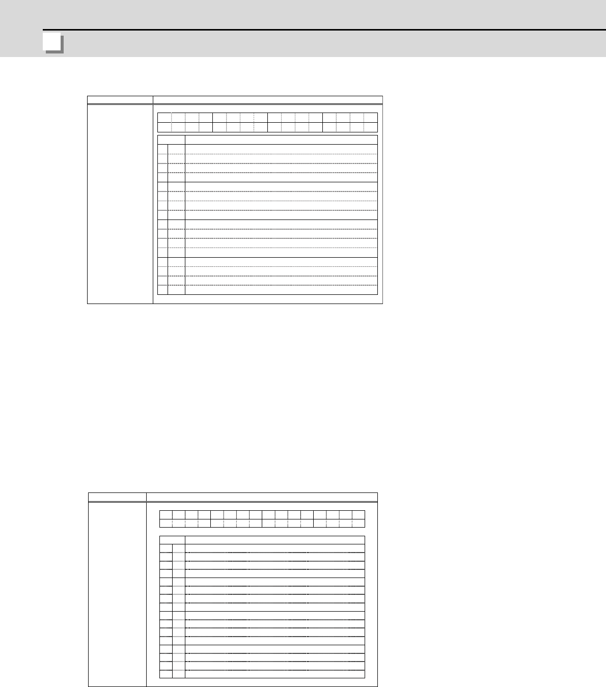
(3) Servo control output 3
bit0. In control axis detachment (AXF)
The control axis is being detached at AXF=1.
(Note) The bits other than those above are used for maintenance.
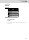
(4) Servo control output 4
This is used for maintenance.
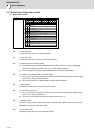
(5) Servo control output 5
This is used for maintenance.
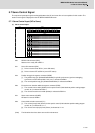
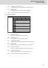
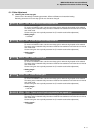
(6) Servo control output 6
bit0. In OMR-FF control (OMRFF)
OMRFF=1 (enabled) if OMR-FF control is enabled.
bit8. In drivers communication control (DD1)
DD1=1 (enabled) if high-speed synchronous tapping control is enabled.
(Note) The bits other than those above are used for maintenance.
Name
Details
Servo control output 3
F
E
D
C
B
A
9
8
7
6
5
4
3
2
1
0
AXF
bit
Details
0
AXF
In control axis detachment
1
-
(For maintenance)
2
-
(For maintenance)
3
-
(For maintenance)
4
-
(For maintenance)
5
-
(For maintenance)
6
-
(For maintenance)
7
-
(For maintenance)
8
-
(For maintenance)
9
-
(For maintenance)
A
-
(For maintenance)
B
-
(For maintenance)
C
-
(For maintenance)
D
-
(For maintenance)
E
-
(For maintenance)
F
-
(For maintenance)
FEDCBA9876543210
bit
0
1
2
3
4
5
6
7
8
9
A
B
C
D
E
F
DD1
-
-
-
-
-
-
-
-
-
-
-
-
-
-
DD1
OMRFF
OMRFF
Name
Details
Servo control output 6
Details
In drivers communication control
In OMR-FF control
(For maintenance)
(For maintenance)
(For maintenance)
(For maintenance)
(For maintenance)
(For maintenance)
(For maintenance)
(For maintenance)
(For maintenance)
(For maintenance)
(For maintenance)
(For maintenance)
(For maintenance)
(For maintenance)