


6 - 22
6 Spindle Adjustment
MITSUBISHI CNC
【#1281(PR)】 ext17
bit5: High-speed synchronous tapping valid
Select whether to enable the high-speed synchronous tapping.
0: Disable
1: Enable
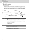
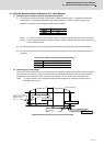
【#3120】 staptr Time constant reduction rate in high-speed synchronous tapping
When performing high-speed synchronous tapping control (#1281/bit5), set the reduction rate of the
time constant compared to the time constant in normal synchronous tapping.
(Setting "0"or "100" will be regarded as reduction rate zero, so the time constant won't be reduced.)
E.g.) When set to "10", time constant in high-speed synchronous tapping will be 90% of that in
normal synchronous tapping.
---Setting range---
0 to 100(%)
6.1.7 Spindle C Axis Adjustment (For Lathe System)
(1) Setting the gain
For spindle C axis speed loop gain, SP008 (speed loop gain 2), speed loop gain set 2, which consists of SP009
(speed loop lead compensation 2), and SP010 (speed loop delay compensation 2), is used. Thus, SP035 has to be
set as follows. For position loop gain, set standard 33 to SP002 (position loop gain, interpolation mode).
<Related servo parameters>
Set the spindle and interpolation axis.
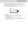
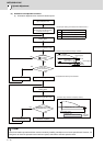
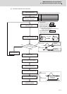
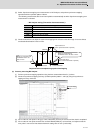
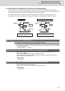
(2) Gain adjustment and accuracy test during C axis operation
[1] Set the "Time-series data measurement" with NC Analyzer as follows during stopped in C axis mode (servo
ON status) or when executing cutting feed with G01 F20. Then check the droop fluctuation is within 10°/1000.
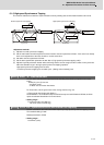
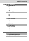
< NC Analyzer setting (Time-series data measurement) >
Offset is 2.5V.
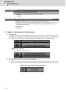
Parameter Setting value
SP002 33
SP008 SP005 setting value set in "Basic Adjustments" (Initial setting value: 150)
SP009 1900
SP010 0
SP035 0200: Speed loop gain set 2 selection (validate bit9)
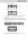
Parameter Setting value
SV003 Set the same value as spindle parameter "SP002"
SV004 Set it when using SHG control (when not using, set to "0" )
SV057 Set it when using SHG control (when not using, set to "0" )
Get Waveform type
CH1 Position droop
CH2 Current command