


4 - 109
MDS-D2/DH2 Series Instruction Manual
4.3 Setting the Initial Parameters for the Spindle Drive Unit
【#3029】 tapsel Asynchronous tap gear selection
Select the speed which is compared with S command at gear selection when using asynchronous
tapping control with the spindle which performs gear changeover.
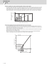
0: Synchronous tapping 1st step rotation speed (stap)--- Multi-step acceleration/deceleration is not
used.
1: Maximum speed (smax)--- Multi-step acceleration/deceleration is used.
This parameter is enabled only when "#1272 ext08/bit1 is 1".
【#3030】
Not used. Set to "0".
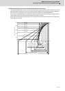
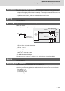
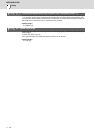
【#3031(PR)】 smcp_no Drive unit I/F channel No. (spindle)
Set the interface channel No. of CNC control unit to which the spindle is connected and the axis No.
within each channel.
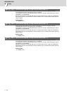
Set this parameter in 4-digit (hexadecimal) format.
HEX-4 : Drive unit interface channel No.
HEX-3 : Not used. Set to "0".
HEX-2, 1 : Axis No.
For an analog spindle, set to "0000".
---Setting range---
0000, 1001 to 1010, 2001 to 2010
- For MDS-DM2-SPV2/SPV3 Series
These drive units have no rotary switches for axis No. selection.
The spindle axis No. is fixed to 1st axis, so set "01" as the number of axes. (last 2 digits).
【#3032】
Not used. Set to "0".
【#3035(PR)】 spunit Output unit
Select the data unit for communication with the spindle drive unit.
This selection is applied to the data communicated between the NC and spindle drive unit as well as
the spindle movement data. Although the standard setting is B (0.001deg), set the same value as
"#1004 ctrl_unit" when using Spindle/C axis control.
B: 0.001deg (1μm)
C: 0.0001deg (0.1μm)
D: 0.00001deg (10nm)
E: 0.000001deg (1nm)
12
3
1234HEX-
0
Number of axes
Interface channel
No.
Channel No.=1
Channel No.=2
Channel No.=m
Axis No.=
12
n
Axis No.=
Rotary switch settings
CNC
control
unit
Spindle
drive
unit