


2 - 27
MDS-D2/DH2 Series Instruction Manual
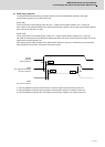
2.5 Motor and Encoder Connection
2.5.3 Connection of the Speed Command Synchronization Control System
Connecting the position command synchronous control system, connect each system as an independent axis.
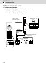
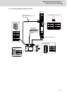
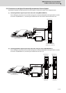
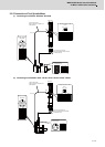
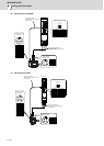
(1) Connecting SIN wave signal output linear scale (when using MDS-D2/DH2-V2)
For the FB signal of the linear scale, the SIN wave signal is converted to Mitsubishi serial signal with the encoder
conversion unit (MDS-B-HR-11), and that signal is divided to each axis control inside the 2-axis drive unit.
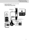
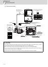
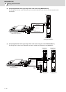
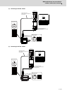
(2) Connecting SIN wave signal output linear scale (when using two units of MDS-D2/DH2-V1)
For the FB signal of the linear scale, the SIN wave signal is converted to Mitsubishi serial signal with the encoder
conversion unit (MDS-B-HR-12), and that signal is divided to each drive unit.
MDS-D2/DH2-V2
CN2M
CN2L
CN3L
CON3
CON4
CON1
CON2
MDS-B-HR-11
Encoder conversion unit
Cable
prepared
by user
Linear scale
( SIN wave signal output )
Encoder type setting
Primary axis: SV025=A2xx
Secondary axis: SV025=D2xx
CNV2E cable
Max. 30m
CNV2E cable
Max. 30m
CNV2E-HP
cable
Max. 30m
Primary axis
Secondary axis
CN2L
CN3L
CN2L
CN3L
CON3
CON4
CON1
CON2
MDS-D2/DH2-V1 MDS-D2/DH2-V1
Primary axis
Secondary axis
MDS-B-HR-12
Encoder interface unit
Cable
prepared
by user
Linear scale
( SIN wave signal output )
Encoder type setting
SV025=A2xx
CNV2E cable
Max. 30m
CNV2E cable
Max. 30m
Primary axis
Secondary axis
CNV2E-HP
cable
Max. 30m
Encoder type setting
SV025=D2xx