


2 - 37
MDS-D2/DH2 Series Instruction Manual
2.7 Wiring of the Motor Brake
2.7 Wiring of the Motor Brake
2.7.1 Wiring of the Motor Magnetic Brake
The magnetic brake of servo motors with a magnetic brake is controlled by the motor brake control connector (CN20) on
the servo drive unit. The servo drive unit releases the brake when the motor is ON.
(Servo ON means when torque is generated in the motor.)
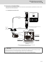
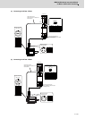
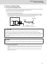
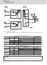
(1) Motor brake control connector output circuit
As shown in the illustration below, an external power supply circuit is controlled by the CN20 connector output.
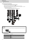
Dynamic brake unit is controlled simultaneously for the servo drive unit with the capacity of MDS-D2-V1-320W or
larger and MDS-DH2-V1-160W or larger. Refer to "Dynamic brake unit wiring" for details.
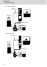
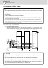
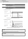
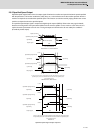
(2) Motor brake release sequence
The motor brake control connector (CN20: MBR) releases the magnetic brake in the sequences in the following
drawing when canceling the emergency stop. The brake is released after the start of the power ON to the servo
motor.
If the power of the power supply unit has been charged by the servo parameter setting, the time to the Ready
completion can be reduced.
CAUTION
1. Always install a surge absorber near the motor's brake terminal to eliminate noise and protect the contacts.
2. The brakes cannot be released just by connecting the CN20 and motor brake terminal. 24VDC must be supplied.
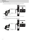
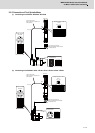
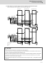
3. When controlling motor brakes of multiple axes in 2-axis or 3-axis drive unit, connect the CN20 output circuits in parallel.
4. For the 24V power supply used in the motor brake circuit, use the one separated from the 24V power supply for the
control circuit.
POINT
To ensure safety in an emergency, make sure that the magnetic brakes are applied in sequence with the emergency stop
switch.
CN20
3
MBR
2
DBR
1
P24
MDS-D2/DH2-V1/V2/V3
stop switch
24VDC
Always install
a surge absorber.
Brake
absorber
(Unit internal relay specification: 5A 30Vdc/8A 250Vac)
Emergency
Surge