


5 - 63
MDS-D2/DH2 Series Instruction Manual
5.6 Protective Functions
<Setting and adjustment methods>
[1] Confirm that SHG control is active. Collision detection function is valid only during SHG control.
[2] Set the axis unbalanced torque to the torque offset (SV032: TOF). (Refer to "Measuring unbalance torque and
frictional torque" for details on measuring the unbalance torque.)
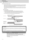
[3] Measure the frictional torque and set in the frictional torque (SV045: TRUB). Carry out reciprocation operation
(approx. F1000) with the axis to be adjusted, and measure the load current % when the axis is fed at the
constant speed on the NC SERVO MONITOR screen. This frictional torque is expressed with the following
expression.
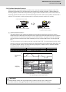
[4] Set SV035: SSF4.clt (bitF) to 1 for the axis being adjusted, and move in both directions with JOG, etc., at the
rapid traverse rate. When the load inertia ratio display on the NC SERVO MONITOR screen has stabilized, set
that value for the torque estimated gain (SV059: TCNV). Return SV035: SSF4.clt (bitF) to 0.
[5] If the acceleration/deceleration time is short, and the current is limited, set SV035: SSF4.c12n (bitB) to 1 to
invalidate collision detection method 2.
[6] Adjust the collision detection level (SV060: TLMT). First set 100. If operation at the rapid traverse rate results
in an alarm, increase the setting value by approx. 20. If an alarm does not occur, lower the setting value by
approx. 10. The estimated disturbance torque value on the servo monitor screen will indicate the estimated
disturbance torque peak value for the latest two seconds. This value can be used as reference. Set the final
setting value to a value approx. 1.5-fold the limit value at which an alarm does not occur.
[7] Divide the maximum cutting load with the value set for the collision detection level (SV060: TLMT). (Round up
the decimal) Set this value in SV035: SSF4.clG1 (bitC-E).
(Example) For maximum cutting load: 200%, SV060: TLMT setting value: 80%
200/80=2.5 -> The detection level is 3 (-fold), so set SV035:SSF4 to "3xxx".
[8] Set the retracting torque when the a collision is detected to SV035: SSF4.cltq (bit8,9).
(Example) To set the retracting torque to 70% of the motor maximum torque:
Set SV035:SSF4 to "x3xx".
【#2232】 SV032 TOF Torque offset
Set the unbalance torque on vertical axis and inclined axis.
When the vertical axis pull up function is enabled, the pull up compensation direction is determined
by this parameter's sign. When set to "0", the vertical axis pull up will not be executed.
This can be used for speed loop delay compensation and collision detection function.
To use load inertia estimation function (drive monitor display), set this parameter, friction torque
(SV045) and load inertia display enabling flag(SV035/bitF).
---Setting range---
-100 to 100 (Stall current %)
2
=
(+ feed load current %) - (- feed load current %)
Frictional torque (%)