


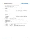
Call router configuration task list 512
SmartWare Software Configuration Guide 40 • Call router configuration
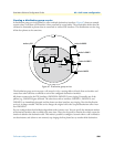
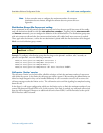
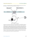
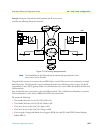
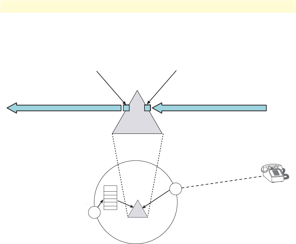
port (see figure 72). Each of these interfaces is responsible for one of the two independent calls. The listener
port terminates the “FXS call” and the dialer port terminates the “RTP call.”
Figure 72. Bridge services diagram
The listener port interface listens to the FXS interface of the SmartNode for an active FXS–FXO connection. It
recognizes an active connection by detecting current in the FXS–FXO loop, and the FXS call is established.
The dialer port interface attempts to make and keep an RTP connection session or call with a dialer port in a
remote SmartNode. It is called an RTP call. This connection is over the IP network. The listener port and the
dialer port both try to keep their individual calls up and operating at all times. However if the listener port
loses its connection (that is, its call), the dialer port does not disconnect its RTP call but remains connected to
the other SmartNode’s dialer port. Similarly, if the local dialer port loses its connection with the remote Smart-
Node’s dialer port, the SmartNode’s listener port does not disconnect its FXS call but remains connected to the
FXO device. Though the calls operate independently, they operate over a single data path from end-to-end.
The dialer port is bound to the Routing Table which is subsequently bound to either an H.323 or SIP inter-
face. The routing table makes the connection to the proper FXS interface.
Listener Port – This port listens for a call from the
FXO device and connects immediately upon
detecting loop current. This is the “Listener Connection.”
Dialer ConnectionDialer Connection
Dialer Port – This port “dials” to the
Dialer Port on the other SmartNode to
create the “Dialer Connection”
BRIDGE
Service
Context CS
Routing
Table
H.323/SIP
Interface
FXS
Interfaces
FXO Device,
always off-hook