


Serial port configuration task list 174
SmartWare Software Configuration Guide 14 • Serial port configuration
Before using the serial interface the hardware port protocol has to be specified. There are two command
options available to select the suitable hardware port protocol:
• v35 for V.35 protocol to be used
• x21 for X.21 protocol to be used
Mode: Administrator execution
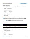
Example: Configuring the hardware port protocol
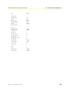
The following example enables X.21 as hardware port protocol for the serial interface on slot 0 and port 0.
Check that Hardware Port is set to X.21 in the command output of
show port serial.
node(cfg)#port serial 0 0
node(prt-ser)[0/0]#hardware-port x21
node(prt-ser)[0/0]#show port serial
Serial Interface Configuration
------------------------------
Port : serial 0 0 0
State : CLOSED
Hardware Port : X.21
Transmit Edge : normal
Port Type : DTE
CRC Type : CRC-16
Max Frame Length: 2048
Recv Threshold : 1
Encapsulation : framerelay
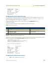
Configuring the active clock edge
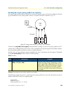
Depending on the system configurations—i.e. when using long cables, with certain modem types or data
rates—synchronization problems may occur on the serial port. In these cases, it may be necessary to configure
the clock edge on which data is transmitted.
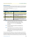
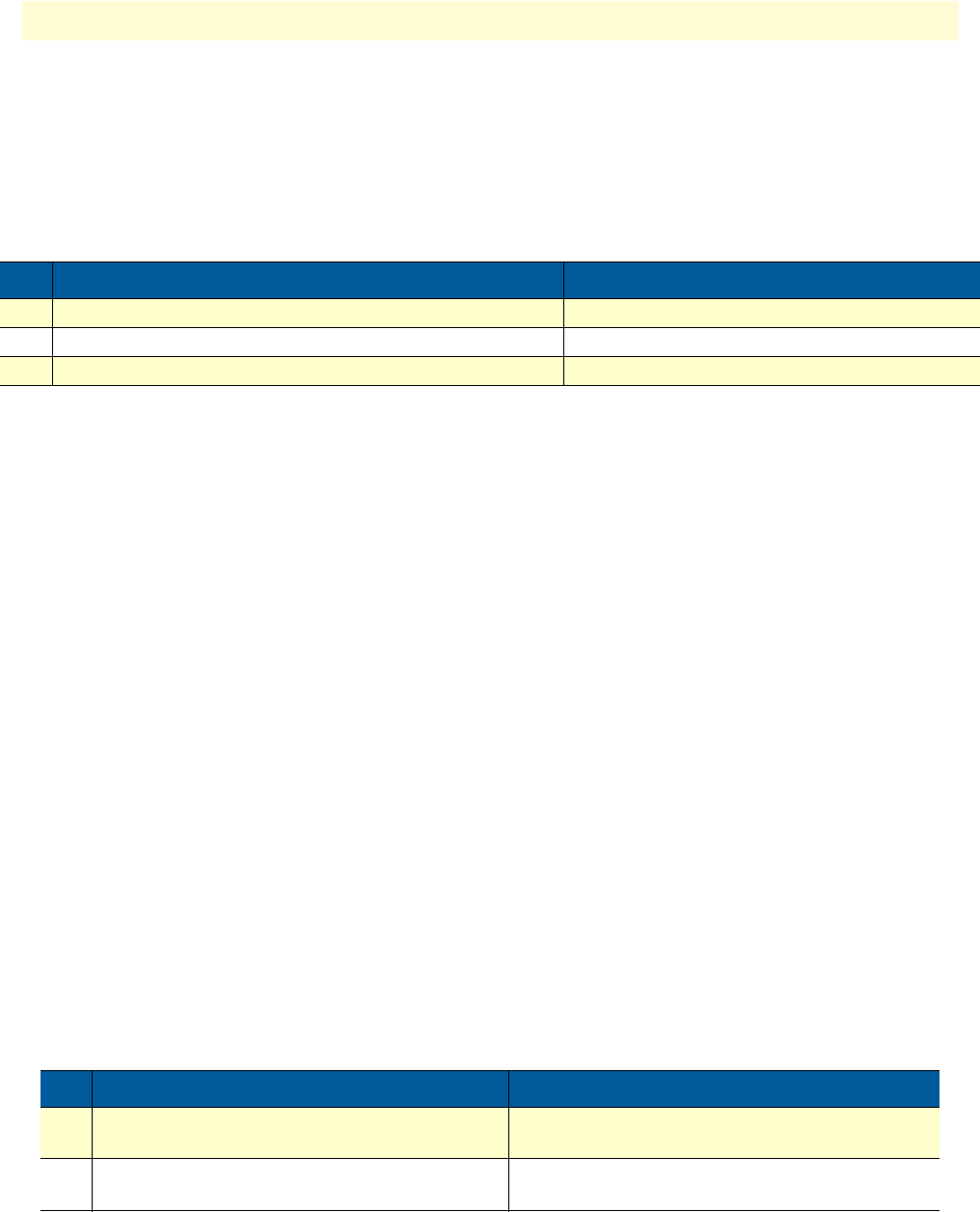
This procedure describes how to set the active clock edge of the serial interface
Mode: Port serial
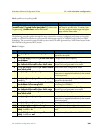
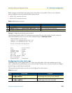
Step Command Purpose
1 node(cfg)#port serial slot port Selects the serial interface on slot and port
2 node(prt-ser)[slot/port]#hardware-port {v35 | x21} Sets the hardware port protocol
3 node(prt-ser)[slot/port]#show port serial Displays the serial interface configuration
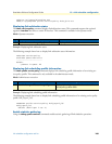
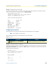
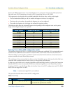
Step Command Purpose
1 node(prt-ser)[slot/port]# transmit-data-
on-edge positive
Configures the serial interface to transmit on the
positive edge of the clock (normal, default).
2 node(prt-ser)[slot/port]# transmit-data-
on-edge negative
Configures the serial interface to transmit on the
negative edge of the clock (inverted).