Frame Relay configuration task list 188
SmartWare Software Configuration Guide 15 • Frame Relay configuration
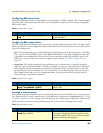
Figure 30. IP Context with logical IP interfaces bound to Ethernet port, serial port PVC 1 and PVC 2
The related IP, serial interface and Frame Relay configuration procedure is listed below. Where necessary, com-
ments are added to the configuration for better understanding.
1. Enter the configuration mode.
node>enable
node#configure
…
2. Set up the IP interface configuration first. Be aware that not all of the necessary settings are listed below.
node(cfg)#context ip router
node(ctx-ip)[router]#interface external
node(if-ip)[external]#interface internal
node(if-ip)[internal]#interface lan
node(if-ip)[lan]#exit
node(ctx-ip)[router]#interface internal
node(if-ip)[internal]#ipaddress 192.168.3.1 255.255.255.0
node(if-ip)[internal]#interface external
node(if-ip)[external]#ipaddress 192.168.2.1 255.255.255.0
node(if-ip)[external]#interface lan
node(if-ip)[lan]#ipaddress 192.168.1.1 255.255.255.0
…
3. Define a voice profile which gives priority to voice packets. Set the rate limit according to the bandwidth
available for voice and data on PVC 1 (512kBits/s in this case).
node(cfg)#profile service-policy VoicePrio
node(pf-srvpl)[VoicePr~]#rate-limit 512
node(pf-srvpl)[VoicePr~]#source class local-voice
node(src)[local-v~]#priority
node(src)[local-v~]#source class local-default
node(src)[local-d~]#priority
node(src)[local-d~]#source class default
…