


Introduction 214
SmartWare Software Configuration Guide 18 • ISDN Overview
The S reference point is on the subscriber interface. This is the typical 4-wire connection between an ISDN
phone and an ISDN PBX. Be aware that many ISDN PBX vendors use non-standard proprietary 2-wire inter-
faces to connect the Terminals to the PBX.
The T reference point is on the trunk interface of a PBX. This is the standard 4-wire interface between the PBX
and the network termination unit (NTU) also known as NT1 in standard terminology. The ISDN layer 2 pro-
tocol at this point is in point-to-point mode between the NTU and the PBX.
The 4-wire layer 1 specification S and T interfaces is foreseen for in-house installations and carries a maximum
of 150 meters.
The S/T reference point is on a point-to-multipoint S-Bus. Here several terminals are connected directly to the
same BRI NTU. The S and T reference points are “collapsed”. The NT2 is not represented by any equipment
unit.
The U reference point is on the transmission side of the NTU designed to carry the ISDN line over the last
mile. For basic rate interfaces this is typically a DSL technology working on legacy copper pairs over a distance
up to 12 kilometers. For primary rate lines, DSL, coax and fiber transmission is in use. In most European
countries the U interface is not accessible to the subscriber, the operator always provides the NT1. In the US
and some other countries the NT1 can be integrated into the NT2, i.e. the PBX is connected directly to the U
interface.
The V reference point is typically a y-wire interface between the line card of the public switch and the 2 Mbps
transmission equipment which transports the PRI signal over copper (DSL), coax or fiber.
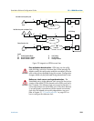
Possible SmartNode port configurations
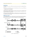
The SmartNode ISDN ports can be configured for connection to S, T, S/T, and V interfaces. Refer to
figure 33, which illustrates some of the possible network integration options.
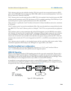
ISDN UNI Signaling
ISDN is a User-Network Interface (UNI) signaling protocol with a user and a network side. The user side is
implemented in ISDN terminals (phones, terminal adapters, etc.) while the network side is implemented in
the exchange switches of the network operator. Both sides have different signaling states and messages. Smart-
Ware ISDN ports can be configured to work as user (USR) or network (NET) interfaces.
A SmartNode in some applications does not replace a standard ISDN equipment (PBX or Terminal) but is
inserted between an existing NT and PBX. In such cases the SmartNode ISDN ports are configured to operate
the opposite side of the connected equipment as illustrated in figure 33.
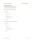
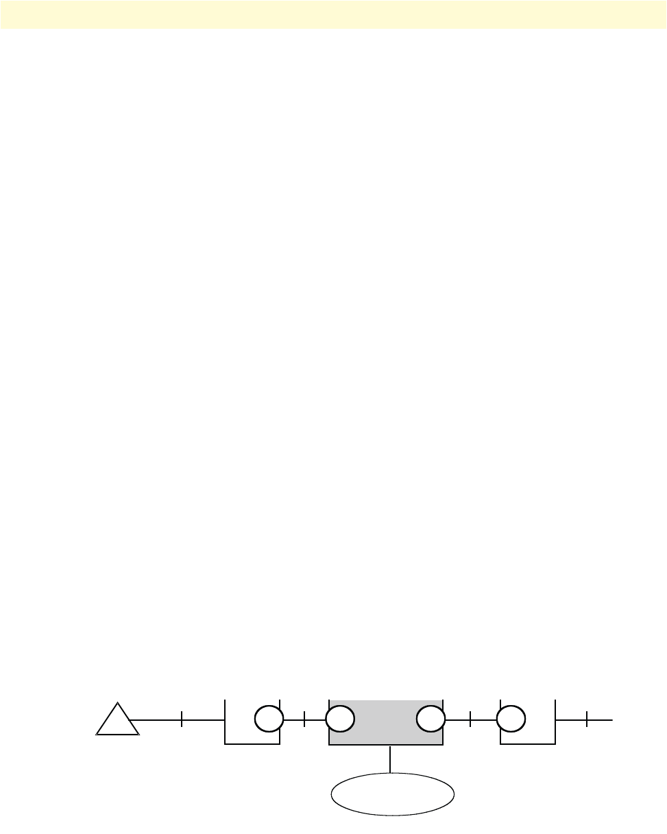
Figure 32. ISDN signaling side
S UT
PBX
Legend:
USR User Side Signaling
NET Network Side Signaling
TE
Phone
NT2 NT1
T
NodeUSR NET NETUSR
IP Network