


ISDN Configuration Concept 216
SmartWare Software Configuration Guide 18 • ISDN Overview
ISDN Configuration Concept
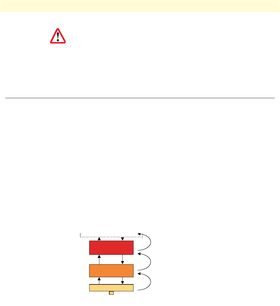
ISDN Layering
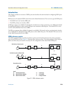
ISDN consists of 3 layers. Each layer has its own parameters that need to be configured.
• Layer 1, often called the physical layer, is responsible to transport single bits between two systems. Layer 1
does not guarantee that a message can be transmitted without errors.
Parameters: Clock mode, line codes.
• Layer 2 allows a station to reliably send messages to another station using the D channel. Layer 2 imple-
ments flow control, error detection and correction (retransmission) as well as addressing mechanism to
direct messages to individual devices.
Parameters: point-to-point or point-to-multipoint mode, network/user side, permanent layer 2 enabled.
• Layer 3 does send and receive application level messages (i.e. call control). It cares for sending broadcast
messages and collecting the individual results of the attached devices. It also handles the assignment of the B
channels.
Parameters: network/user side, protocol (i.e. DSS1), maximum number of channels.
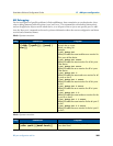
Figure 34. ISDN layering model
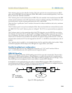
The layered model of ISDN is reflected in the configuration by the use of different modes for each layer. The
layers are connected by using encapsulations and bindings. The encapsulation defines what the next higher
layer protocol will be. On the topmost layer, the binding finally selects a logical interface to connect the
port to. For more information how to configure and setup the physical ports for ISDN, please see Chapter 17,
“BRI port configuration” on page 205 and Chapter 16, “PRI port configuration” on page 191. Detailed infor-
mation about Q.921 and Q.931 configuration are available in Chapter 19, “ISDN configuration” on
page 217.
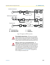
Connector pin-out and short circuits—Some of the Smart-
Node ISDN BRI ports are configurable to operate as network or
terminal ports. The pin-out of the sockets is switched according to
this configuration. Wrong port configurations, wrong cabling or
wrong connections to neighboring equipment can lead to short
circuits in the BRI line powering. Refer to the HW installation
guide and the port configuration sections below to avoid miscon-
figurations.
IMPORTAN
T
Encapsulation: cc-
Bind: <call control interface>
Encapsulation: q931
Encapsulation: q921
Phys. Port
Layer 1
Layer 2 (Q.921)
Layer 3 (Q.931)
Call
Control