


Frame Relay configuration task list 180
SmartWare Software Configuration Guide 15 • Frame Relay configuration
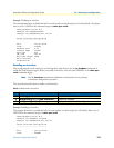
Enabling fragmentation
FRF.12 interface and end-to-end fragmentation of large IP packets is supported to reduce the delay imposed
on voice packets on slow links (less than 512 kbps). As opposed to IP fragmentation, Frame Relay fragmenta-
tion is transparent to the IP layer. This leaves IP packets unchanged, which may be important for IP-based
applications susceptible to IP fragmentation.
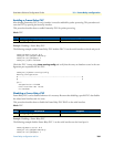
This procedure describes how to enable Frame Relay fragmentation
Mode: Frame Relay
Note For proper functioning, do not specify a scheduler mode (burst-shaper,
burst-WFQ, shaper, WFQ) for the Frame Relay service policy profile. Fur-
thermore, do not use the Frame Relay service policy profile on the IP layer,
but rather on the Frame Relay layer (mode framerelay). Make sure voice traf-
fic is being given priority over data (command
source class local-
voice priority
).
Note FRF.12 end-to-end fragmentation and FRF.12 interface fragmentation are
incompatible. Thus make sure that both ends of a Frame Relay link run the
same fragmentation mode.
Note When running data and voice over a Frame Relay link, it is advisable to only
configure fragmentation for the PVC that carries data traffic. This way, frag-
mentation protocol overhead and fragmentation processing overhead is only
spent for data traffic—voice packets (whose length should be smaller than the
fragmentation length) do not consume processing power and protocol over-
head for fragmentation.
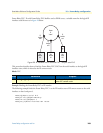
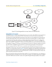
The purpose of end-to-end FRF.12 fragmentation is to support real-time and non-real-time data packets on
lower-speed links without causing excessive delay to the real-time data. The FRF.12 Implementation Agree-
ment defines FRF.12 fragmentation. This standard was developed to allow long data frames to be fragmented
into smaller pieces (fragments) and interleaved with real-time frames. In this way, real-time and non-real-time
data frames can be carried together on lower-speed links without causing excessive delay to the real-time traffic.
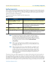
Step Command Purpose
1 node(frm-rel)[slot/port]#use pro-
file service-policy name out
Uses the previously defined service policy profile on Frame
Relay layer (and not on IP interface level) in outward direc-
tion.
2 node(frm-rel)[slot/port]#frag-
ment size
Defines the maximum size (in Bytes) of the Frame Relay pay-
load (excluding Frame Relay header and trailer overhead)
for all PVCs (FRF.12 interface fragmentation).
See also the table below
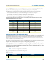
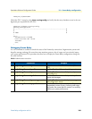
3 node(frm-rel)[slot/port]#pvc dlci Enters the PVC configuration mode by assigning a DLCI num-
ber to be used on the specified virtual circuit.
4 node(pvc)[dlci]#fragment size Defines the maximum size (in bytes) of the Frame Relay pay-
load (excluding Frame Relay header and trailer overhead)
for this PVC only (FRF.12 end-to-end fragmentation).
See also the table below