


Frame Relay configuration task list 181
SmartWare Software Configuration Guide 15 • Frame Relay configuration
End-to-end FRF.12 fragmentation is recommended for use on permanent virtual circuits (PVCs) that share
links with other PVCs transporting voice and on PVCs transporting Voice over IP (VoIP).
The fragmentation size depends on the available bandwidth, the chosen codec, and its packet length:
• The less bandwidth available per call, the smaller the fragment size has to be configured.
• The shorter the voice packets, the smaller the fragment size can be configured.
• The smaller the fragment size, the bigger the overhead for long data packets.
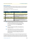
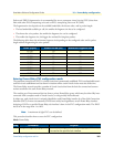
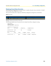
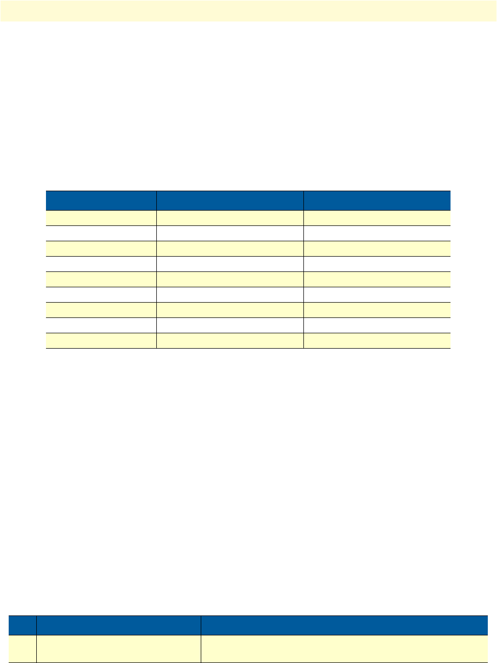
The following table shows the minimum fragment size depending on the configured codec and its packet
length without fragmenting the voice packets:
Entering Frame Relay PVC configuration mode
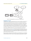
The permanent virtual circuit (PVC) is a virtual circuit that is permanently established. PVCs save bandwidth associ-
ated with circuit establishment and tear down in situations where certain virtual circuits must exist all the time.
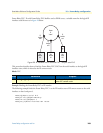
The Frame Relay network provides a number of virtual circuits that form the basis for connections between
stations attached to the same Frame Relay network.
The resulting set of interconnected devices forms a private Frame Relay group, which may be either fully inter-
connected with a complete mesh of virtual circuits, or only partially interconnected.
In either case, each virtual circuit is uniquely identified at each Frame Relay interface by a Data Link Connection
Identifier (DLCI). In most circumstances, DLCIs have strictly local significance at each Frame Relay interface.
Assigning a DLCI to a specified Frame Relay sub interface is done in the PVC configuration mode. The DLCI
has to be in the range from 1 to 1022.
Note A maximum of eight PVCs can be defined.
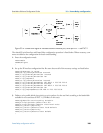
This procedure describes how to enter the PVC configuration.
Mode: Frame Relay
Codec (bytes) Packet Period (ms) Minimum Fragment Size
G.729 10 52
G.729 20 62
G.729 30 72
G.723 30 66
G.723 60 90
G.723 90 114
G.711 10 122
G.711 20 202
G.711 30 282
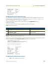
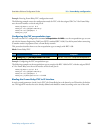
Step Command Purpose
1 node(frm-rel)[slot/port]#pvc dlci Enters the PVC configuration mode by assigning a DLCI number
to be used on the specified sub interface