


MERLIN LEGEND Communications System Release 6.0
System Programming
555-660-111
Issue 1
February 1998
Programming Procedures
Page 4-29Lines and Trunks
4
Lines and Trunks 4
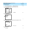
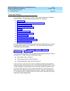
The procedures in this section are used to assign optional features to individual
lines and trunks. The following optional features can be assigned:
■ Type of Trunk
■ Outmode Signaling for Loop- or Ground-Start Trunks
■ Rotary Trunk Digit Transfer
■ Disconnect Signaling Reliability
■ Toll Type
■ Hold Disconnect Interval
■ Principal User for Personal Line
■ QCC Queue Priority
■ QCC Operator to Receive Calls
■ Incoming Call Line Identification Delay
■ Trunks to Pools Assignment
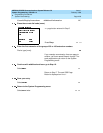
The Copy Options feature (described at the end of this section) allows you to copy
several optional features from an idle trunk. This option eliminates the need to
individually enter each feature.
Separate sections cover “DS1 Facilities,” “Tie Trunks,” “DID Trunks,”
“PRI Facilities,” and “BRI Facilities.”
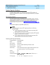
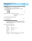
A slot is the physical location of the individual module on the control unit. There is
a maximum of 17 slots which are numbered as follows:
■ Basic carrier: slots 1 through 5
■ First expansion carrier: slots 6 through 11
■ Second expansion carrier: slots 12 through 17
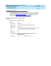
A port is a line or trunk jack on the module. Individual modules support different
numbers of ports. On any module, port 1 is the lowest physical jack position. Lines
connect equipment to the switch and trunks connect a switch to a switch. Lines
and trunks have logical IDs, unique numeric identifiers for each extension and
trunk jack in the communications system control unit. Lines are numbered from 1
to 144, while trunks are numbered from 801 to 880. An MLX extension port has 2
logical IDs for each physical jack.