MERLIN LEGEND Communications System Release 6.0
System Programming
555-660-111
Issue 1
February 1998
Button Diagrams
Page E-4
E
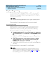
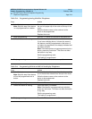
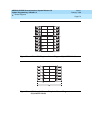
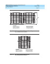
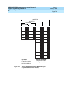
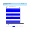
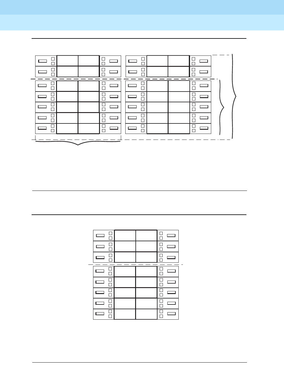
Figure E–5. MLX-20L and MLX-28D Telephone Button Diagram
(Key and Behind Switch Modes)
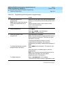
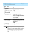
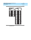
Figure E–6. MLX-16DP Telephone Button Diagram
(Key and Behind Switch Modes)
28
20
27
26
25
24
23
22
21
20
19
18
17
16
15
28
Icom
Voice
Icom
Ring
10
9
8
7
14
13
12
11
6
5
4
3
2
1
10
Key Mode:
Up to 8 personal line
buttons are assigned
beginning at button 3.
Behind Switch Mode:
One prime line button
is assigned to button 3.
15
14
12
11
Icom
Voice
Icom
Ring
10
9
8
7
6
5
4
3
2
1
1613
Key Mode:
Up to 8 personal line
buttons are assigned
beginning at button 3.
Behind Switch Mode:
One prime line button
is assigned to button 3.


