


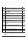
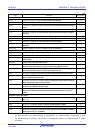
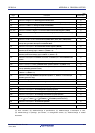
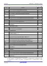
RL78/G1A APPENDIX A REVISION HISTORY
(6/8)
Edition Description Chapter
Deletion of caution 2 in Figure 16-2. Format of Interrupt Request Flag Registers
(IF0L, IF0H, IF1L, IF1H, IF2L, IF2H, IF3L) (128-pin)
Modification of value and addition of note in Table 16-4. Time from Generation of
Maskable Interrupt Until Servicing
Modification of Figure 16-8. Interrupt Request Acknowledgment Timing (Minimum
Time) and Figure 16-9. Interrupt Request Acknowledgment Timing (Maximum
Time)
Modification of Table 16-5. Relationship Between Interrupt Requests Enabled for
Multiple Interrupt Servicing During Interrupt Servicing
Deletion of caution in 16.4.4 Interrupt request hold
CHAPTER 16
INTERRUPT FUNCTION
Change of all
CHAPTER 17 KEY
INTERRUPT FUNCTION
Addition of note 1 and modification of note 2 in Figure 18-3. HALT Mode Release by
Interrupt Request Generation
Modification of description and note in Figure 18-4. HALT Mode Release by Reset
Modification of description in Table 18-2. Operating Statuses in STOP Mode
Modification of note in Figure 18-5. STOP Mode Release by Interrupt Request
Generation
Modification of note in Figure 18-6. STOP Mode Release by Reset
Modification of description in 18.3.3 (1) SNOOZE mode setting and operating
statuses
Modification of description in Table 18-3. Operating Statuses in SNOOZE Mode
CHAPTER 18
STANDBY FUNCTION
Modification of Figures 19-2 to 19-4
Modification of description in Table 19-1. Operation Statuses During Reset Period
Modification of note 2 in Table 19-2. Hardware Statuses After Reset
Acknowledgment
CHAPTER 19 RESET
FUNCTION
Modification of description and notes in Figure 20-2. Timing of Generation of Internal
Reset Signal by Power-on-reset Circuit and Voltage Detector
CHAPTER 20 POWER-
ON-RESET CIRCUIT
Modification of Figure 21-1. Block Diagram of Voltage Detector
Modification of description in Figure 21-2. Format of Voltage Detection Register
(LVIM)
Addition of figure to Table 21-1. LVD Operation Mode and Detection Voltage
Settings for User Option Byte (000C1H)
Modification of Figures 21-4 to 21-6
Addition of description and Figure 21-7, 21-8 to 21.4.3 When used as interrupt and
reset mode
CHAPTER 21
VOLTAGE DETECTOR
Modification of remark in 22.1 Overview of Safety Functions
Addition of description and caution to 22.3.1 Flash memory CRC operation function
(high-speed CRC)
Modification of Figure 22-3. Flowchart of Flash Memory CRC Operation Function
(High-speed CRC)
Rev.0.03
Addition of description and caution to 22.3.2 CRC operation function (general-
purpose CRC)
CHAPTER 22 SAFETY
FUNCTIONS
R01UH0305EJ0200 Rev.2.00 979
Jul 04, 2013