


RL78/G1A CHAPTER 27 BCD CORRECTION CIRCUIT
27.3 BCD Correction Circuit Operation
The basic operation of the BCD correction circuit is as follows.
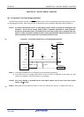
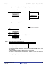
(1) Addition: Calculating the result of adding a BCD code value and another BCD code value by using a
BCD code value
<1> The BCD code value to which addition is performed is stored in the A register.
<2> By adding the value of the A register and the second operand (value of one more BCD code to be added) as
are in binary, the binary operation result is stored in the A register and the correction value is stored in the
BCD correction result register (BCDADJ).
<3> Decimal correction is performed by adding in binary the value of the A register (addition result in binary) and
the BCDADJ register (correction value), and the correction result is stored in the A register and CY flag.
Caution The value read from the BCDADJ register varies depending on the value of the A register
when it is read and those of the CY and AC flags. Therefore, execute the instruction <3>
after the instruction <2> instead of executing any other instructions. To perform BCD
correction in the interrupt enabled state, saving and restoring the A register is required
within the interrupt function. PSW (CY flag and AC flag) is restored by the RETI instruction.
An example is shown below.
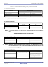
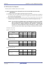
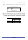
Examples 1: 99 + 89 = 188
Instruction A Register CY Flag AC Flag BCDADJ
Register
MOV A, #99H ; <1>
− − −
99H
ADD A, #89H ; <2>
22H 1 1 66H
ADD A, !BCDADJ ; <3>
−
88H 1 0
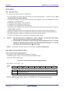
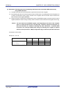
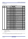
Examples 2: 85 + 15 = 100
Instruction A Register CY Flag AC Flag BCDADJ
Register
MOV A, #85H ; <1>
− − −
85H
ADD A, #15H ; <2>
9AH 0 0 66H
ADD A, !BCDADJ ; <3>
−
00H 1 1
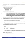
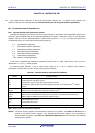
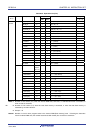
Examples 3: 80 + 80 = 160
Instruction A Register CY Flag AC Flag BCDADJ
Register
MOV A, #80H ; <1>
− − −
80H
ADD A, #80H ; <2>
00H 1 0 60H
ADD A, !BCDADJ ; <3>
−
60H 1 0
R01UH0305EJ0200 Rev.2.00 828
Jul 04, 2013