


RL78/G1A CHAPTER 12 SERIAL ARRAY UNIT
R01UH0305EJ0200 Rev.2.00 414
Jul 04, 2013
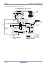
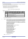
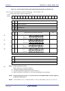
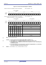
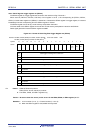
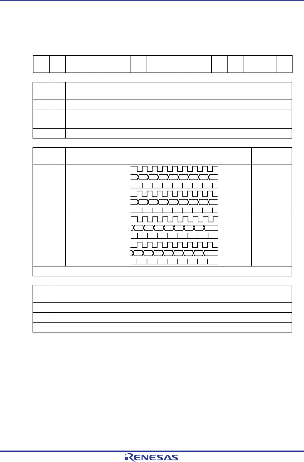
Figure 12-7. Format of Serial Communication Operation Setting Register mn (SCRmn) (1/2)
Address: F0118H, F0119H (SCR00) to F011EH, F011FH (SCR03), After reset: 0087H R/W
F0158H, F0159H (SCR10), F015AH, F015BH (SCR11)
Note 1
Symbol 15 14 13 12 11 10 9 8 7 6 5 4 3 2 1 0
SCRmn
TXE
mn
RXE
mn
DAP
mn
CKP
mn
0
EOC
mn
PTC
mn1
PTC
mn0
DIR
mn
0
SLCm
n1
Note 2
SLC
mn0
0 1
DLSm
n1
Note 3
DLS
mn0
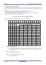
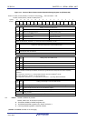
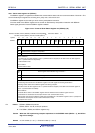
TXE
mn
RXE
mn
Setting of operation mode of channel n
0 0 Disable communication.
0 1 Reception only
1 0 Transmission only
1 1 Transmission/reception
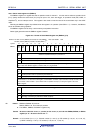
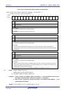
DAP
mn
CKP
mn
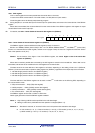
Selection of data and clock phase in CSI mode Type
0 0
D7 D6 D5 D4 D3 D2 D1 D0
SCKp
SOp
SI
p
input timing
1
0 1
D7 D6 D5 D4 D3 D2 D1 D0
SCKp
SOp
SI
p input timing
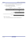
2
1 0
D7 D6 D5 D4 D3 D2 D1 D0
SCKp
SOp
SI
p
input timing
3
1 1
D7 D6 D5 D4 D3 D2 D1 D0
SCKp
SOp
SI
p
input timing
4
Be sure to set DAPmn, CKPmn = 0, 0 in the UART mode and simplified I
2
C mode.
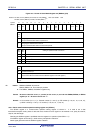
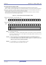
EOC
mn
Mask control of error interrupt signal (INTSREx (x = 0 to 2))
0 Disables generation of error interrupt INTSREx (INTSRx is generated).
1 Enables generation of error interrupt INTSREx (INTSRx is not generated if an error occurs).
Set EOCmn = 0 in the CSI mode, simplified I
2
C mode, and during UART transmission
Note 4
.
Notes 1. SCR00 to SCR03: All products
SCR10, SCR11: 32, 48, and 64-pin products
2. The SCR00, SCR02, and SCR10 registers only.
3. The SCR00 and SCR01 registers only. Others are fixed to 1.
4. When using CSImn not with EOCmn = 0, error interrupt INTSREn may be generated.
Caution Be sure to clear bits 3, 6, and 11 to “0” (Also clear bit 5 of the SCR01, SCR03, or SCR11 register to
0). Be sure to set bit 2 to “1”.
Remark m: Unit number (m = 0, 1), n: Channel number (n = 0 to 3), p: CSI number (p = 00, 01, 10, 11, 20, 21)
<R>
<R>
<R>
<R>
<R>