


RL78/G1A CHAPTER 12 SERIAL ARRAY UNIT
R01UH0305EJ0200 Rev.2.00 477
Jul 04, 2013
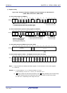
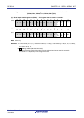
12.5.5 Slave reception
Slave reception is that the RL78 microcontroller receives data from another device in the state of a transfer clock being
input from another device.
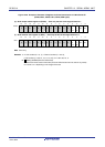
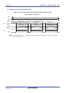
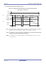
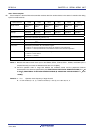
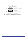
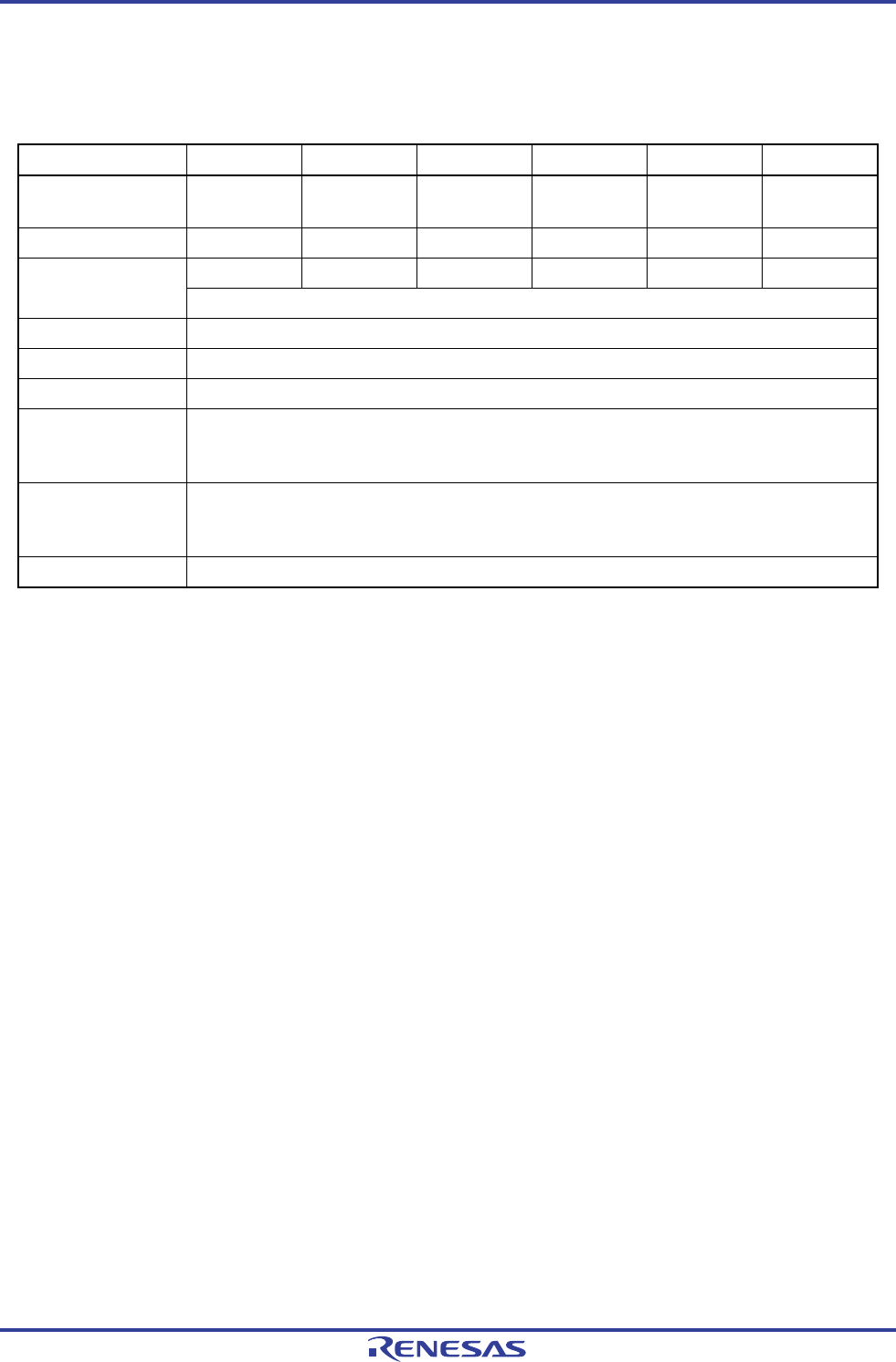
3-Wire Serial I/O CSI00 CSI01 CSI10 CSI11 CSI20 CSI21
Target channel Channel 0 of
SAU0
Channel 1 of
SAU0
Channel 2 of
SAU0
Channel 3 of
SAU0
Channel 0 of
SAU1
Channel 1 of
SAU1
Pins used SCK00, SI00 SCK01, SI01 SCK10, SI10 SCK11, SI11 SCK20, SI20 SCK21, SI21
INTCSI00 INTCSI01 INTCSI10 INTCSI11 INTCSI20 INTCSI21 Interrupt
Transfer end interrupt only (Setting the buffer empty interrupt is prohibited.)
Error detection flag Overrun error detection flag (OVFmn) only
Transfer data length 7 or 8 bits
Transfer rate Max. fMCK/6 [MHz]
Notes 1, 2
Data phase Selectable by the DAPmn bit of the SCRmn register
• DAPmn = 0: Data input starts from the start of the operation of the serial clock.
• DAPmn = 1: Data input starts half a clock before the start of the serial clock operation.
Clock phase Selectable by the CKPmn bit of the SCRmn register
• CKPmn = 0: Non-reverse
• CKPmn = 1: Reverse
Data direction MSB or LSB first
Notes 1. Because the external serial clock input to the SCK00, SCK01, SCK10, SCK11, SCK20, and SCK21 pins is
sampled internally and used, the fastest transfer rate is f
MCK/6 [MHz].
2. Use this operation within a range that satisfies the conditions above and the peripheral functions
characteristic in the electrical specifications (see CHAPTER 29 ELECTRICAL SPECIFICATIONS (T
A = −40
to +85°C), CHAPTER 30 ELECTRICAL SPECIFICATIONS (G: INDUSTRIAL APPLICATIONS TA = −40 to
+105°C)).
Remarks 1. f
MCK: Operation clock frequency of target channel
2. m: Unit number (m = 0, 1), n: Channel number (n = 0 to 3), mn = 00 to 03, 10, 11
<R>