


RL78/G1A CHAPTER 18 STANDBY FUNCTION
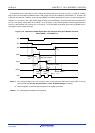
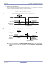
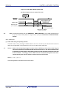
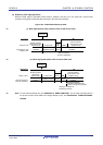
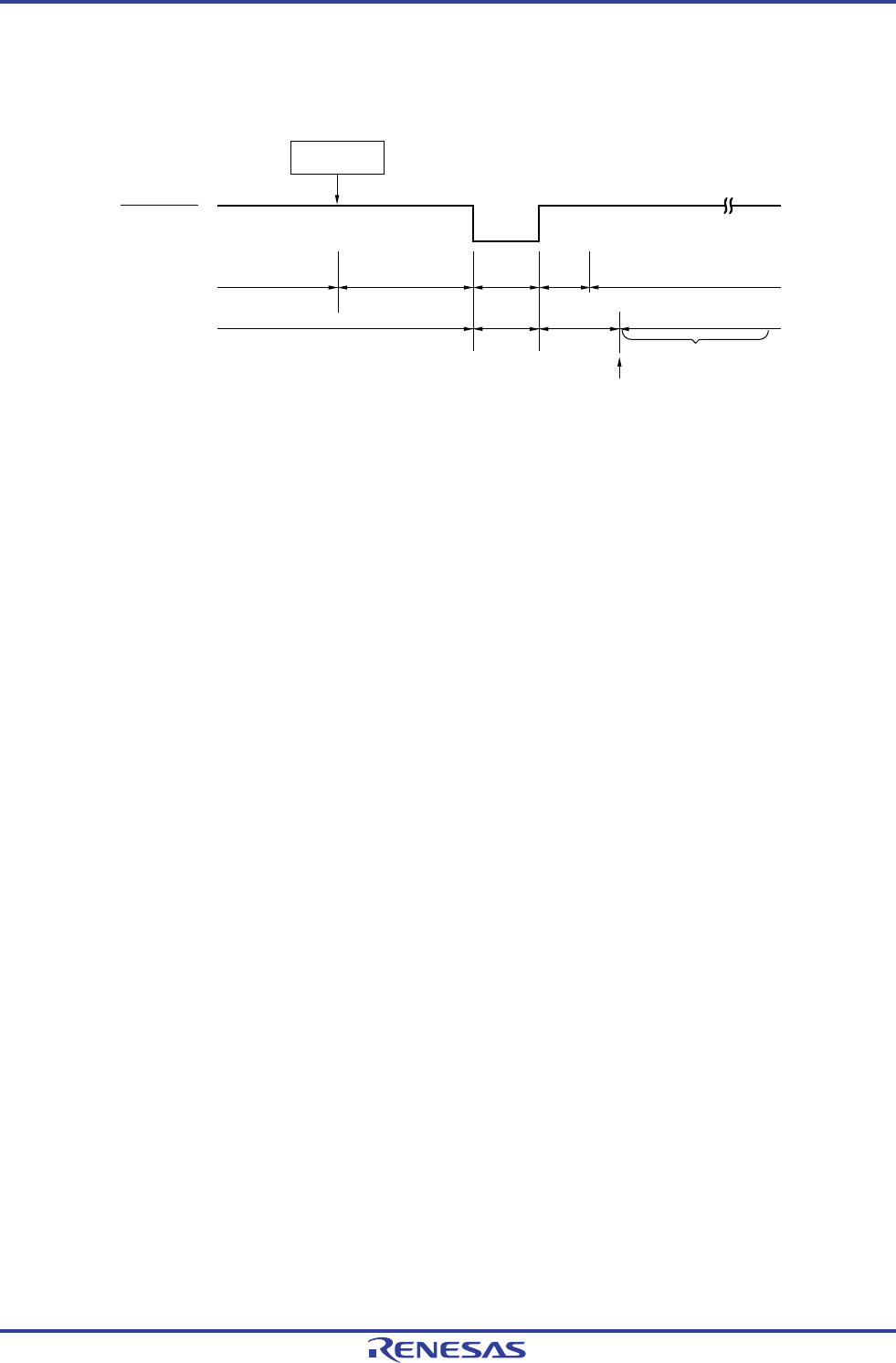
Figure 18-2. HALT Mode Release by Reset (2/2)
(3) When subsystem clock is used as CPU clock
HALT
instruction
Reset signal
Subsystem clock
(XT1 oscillation)
Normal operation
(subsystem clock)
HALT mode
Reset
period
Normal operation mode
(high-speed on-chip
oscillator clock)
Oscillates
Oscillation
stopped
Oscillates
Status of CPU
Oscillation
stopped
Oscillation stabilization time
(check by using OSTC register)
Note
Starting XT1 oscillation is
specified by software.
Note For the reset processing time, see CHAPTER 19 RESET FUNCTION. For the reset processing time of
the power-on-reset circuit (POR) and voltage detector (LVD), see CHAPTER 20 POWER-ON-RESET
CIRCUIT.
<R>
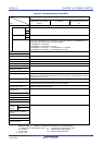
18.3.2 STOP mode
(1) STOP mode setting and operating statuses
The STOP mode is set by executing the STOP instruction, and it can be set only when the CPU clock before the
setting was the high-speed on-chip oscillator clock, X1 clock, or external main system clock.
Caution Because the interrupt request signal is used to clear the STOP mode, if the interrupt mask flag is 0
(the interrupt processing is enabled) and the interrupt request flag is 1 (the interrupt request signal
is generated), the STOP mode is immediately cleared if set when the STOP instruction is executed
in such a situation. Accordingly, once the STOP instruction is executed, the system returns to its
normal operating mode after the elapse of release time from the STOP mode.
<R>
Remark p = 00; q = 0; m = 0
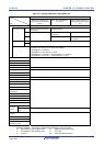
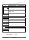
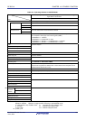
The operating statuses in the STOP mode are shown below.
R01UH0305EJ0200 Rev.2.00 732
Jul 04, 2013