


RL78/G1A CHAPTER 12 SERIAL ARRAY UNIT
R01UH0305EJ0200 Rev.2.00 507
Jul 04, 2013
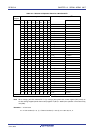
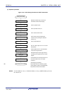
Figure 12-75. Example of Contents of Registers for UART Transmission of UART
(UART0 to UART2) (2/2)
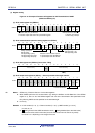
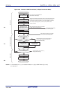
(e) Serial output register m (SOm) … Sets only the bits of the target channel.
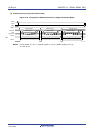
15 14 13 12 11 10 9 8 7 6 5 4 3 2 1 0
SOm
0
0
0
0
CKOm3
Note 1
×
CKOm2
Note 1
×
CKOm1
×
CKOm0
×
0
0
0
0
Som3
Note 1
×
SOm2
Notes 1, 2
0/1
SOm1
×
SOm0
Note 2
0/1
0: Serial data output value is “0”
1: Serial data output value is “1”
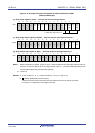
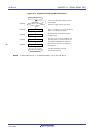
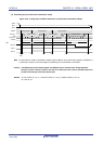
(f) Serial output enable register m (SOEm) … Sets only the bits of the target channel to 1.
15 14 13 12 11 10 9 8 7 6 5 4 3 2 1 0
SOEm
0
0
0
0
0
0
0
0
0
0
0
0
SOEm3
Note 1
×
SOEm2
Note 1
0/1
SOEm1
×
SOEm0
0/1
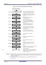
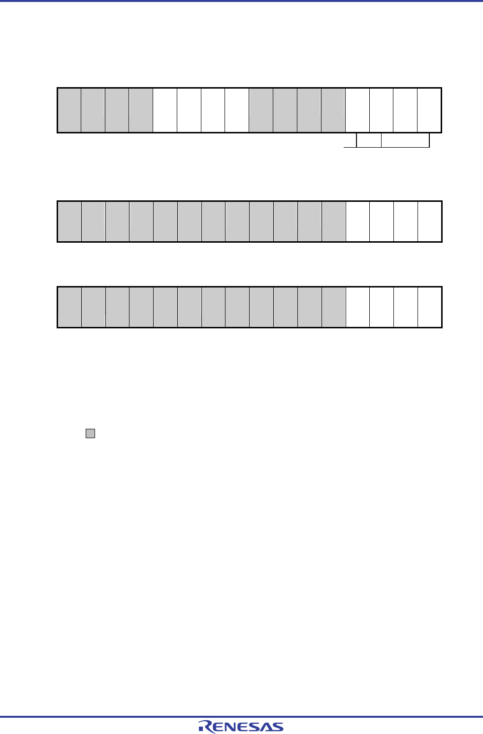
(g) Serial channel start register m (SSm) … Sets only the bits of the target channel to 1.
15 14 13 12 11 10 9 8 7 6 5 4 3 2 1 0
SSm
0
0
0
0
0
0
0
0
0
0
0
0
SSm3
Note 1
×
SSm2
Note 1
0/1
SSm1
×
SSm0
0/1
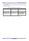
Notes 1. Before transmission is started, be sure to set to 1 when the SOLmn bit of the target channel is set to 0,
and set to 0 when the SOLmn bit of the target channel is set to 1. The value varies depending on the
communication data during communication operation.
2. Unit 0 only
Remarks 1. m: Unit number (m = 0, 1), n: Channel number (n = 0, 2), mn = 00, 02, 10
2. : Setting disabled (set to the initial value)
×: Bit that cannot be used in this mode (set to the initial value when not used in any mode)
0/1: Set to 0 or 1 depending on the usage of the user