


RL78/G1A CHAPTER 19 RESET FUNCTION
CHAPTER 19 RESET FUNCTION
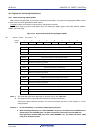
The following seven operations are available to generate a reset signal.
(1) External reset input via RESET pin
(2) Internal reset by watchdog timer program loop detection
(3) Internal reset by comparison of supply voltage and detection voltage of power-on-reset (POR) circuit
(4) Internal reset by comparison of supply voltage of the voltage detector (LVD) and detection voltage
(5) Internal reset by execution of illegal instruction
Note
(6) Internal reset by RAM parity error
(7) Internal reset by illegal-memory access
Jul 04, 2013
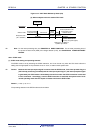
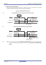
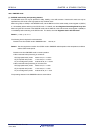
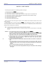
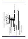
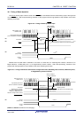
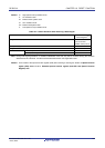
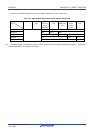
External and internal resets start program execution from the address stored at 0000H and 0001H when the reset
signal is generated.
A reset is effected when a low level is input to the RESET pin, the watchdog timer overflows, or by POR and LVD
circuit voltage detection, execution of illegal instruction
Note
, RAM parity error or illegal-memory access, and each item of
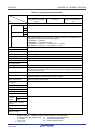
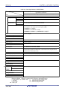
hardware is set to the status shown in Table 19-1.
Note The illegal instruction is generated when instruction code FFH is executed.
Reset by the illegal instruction execution not issued by emulation with the in-circuit emulator or on-chip debug
emulator.
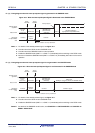
Cautions 1. For an external reset, input a low level for 10
μ
s or more to the RESET pin.
To perform an external reset upon power application, input a low level to the RESET pin, turn
power on, continue to input a low level to the pin for 10
μ
s or more within the operating voltage
range shown in 29.4 or 30.4 AC Characteristics, and then input a high level to the pin.
2. During reset input, the X1 clock, XT1 clock, high-speed on-chip oscillator clock, and low-speed
on-chip oscillator clock stop oscillating. External main system clock input and external
subsystem clock input become invalid.
3. The port pins become the following state because each SFR and 2nd SFR are initialized after
reset.
<R>
• P40: High-impedance during the external reset period or reset period by the POR. High level
during other types of reset or after receiving a reset signal (connected to the internal pull-up
resistor).
• P130: Low level during the reset period or after receiving a reset signal.
• Ports other than P40 and P130: High-impedance during the reset period or after receiving a
reset signal.
R01UH0305EJ0200 Rev.2.00 740