


RL78/G1A CHAPTER 6 TIMER ARRAY UNIT
R01UH0305EJ0200 Rev.2.00 282
Jul 04, 2013
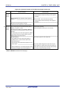
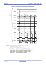
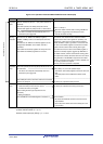
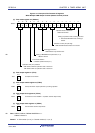
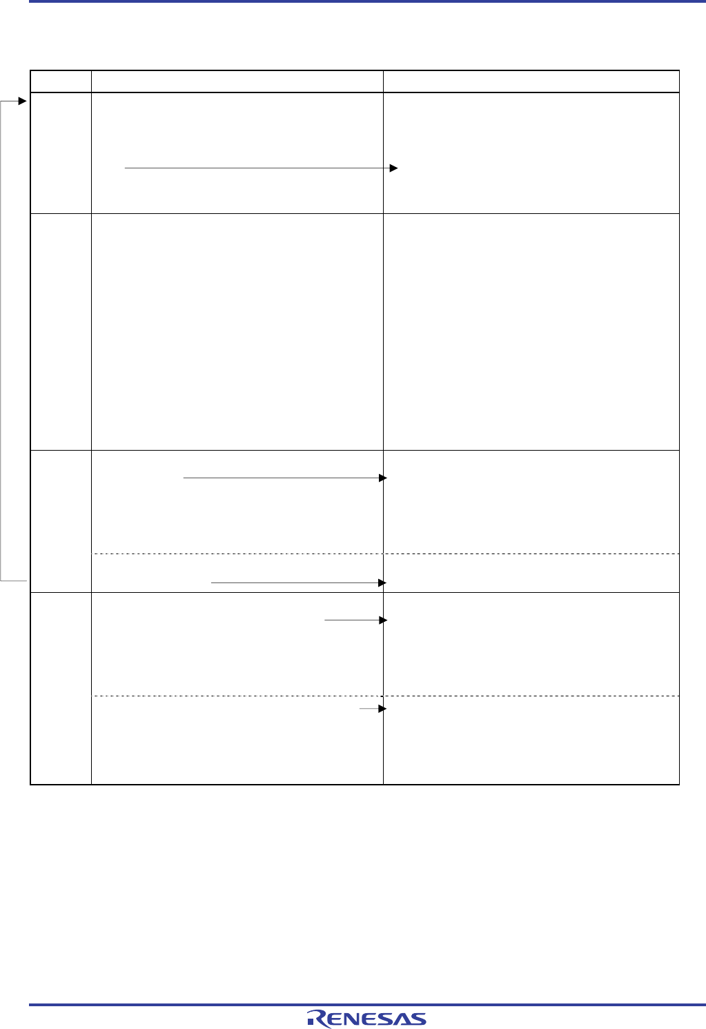
Figure 6-74. Operation Procedure When PWM Function Is Used (2/2)
Software Operation Hardware Status
Operation
start
Sets the TOEmp bit (slave) to 1 (only when operation is
resumed).
The TSmn (master) and TSmp (slave) bits of timer
channel start register m (TSm) are set to 1 at the same
time.
The TSmn and TSmp bits automatically return to 0
because they are trigger bits.
TEmn = 1, TEmp = 1
When the master channel starts counting, INTTMmn is
generated. Triggered by this interrupt, the slave
channel also starts counting.
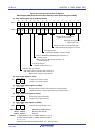
During
operation
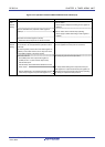
Set values of the TMRmn and TMRmp registers,
TOMmn, TOMmp, TOLmn, and TOLmp bits cannot be
changed.
Set values of the TDRmn and TDRmp registers can be
changed after INTTMmn of the master channel is
generated.
The TCRmn and TCRmp registers can always be read.
The TSRmn and TSRmp registers are not used.
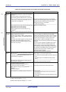
The counter of the master channel loads the TDRmn
register value to timer count register mn (TCRmn), and
counts down. When the count value reaches TCRmn =
0000H, INTTMmn output is generated. At the same time,
the value of the TDRmn register is loaded to the TCRmn
register, and the counter starts counting down again.
At the slave channel, the value of the TDRmp register is
loaded to the TCRmp register, triggered by INTTMmn of
the master channel, and the counter starts counting down.
The output level of TOmp becomes active one count clock
after generation of the INTTMmn output from the master
channel. It becomes inactive when TCRmp = 0000H, and
the counting operation is stopped.
After that, the above operation is repeated.
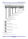
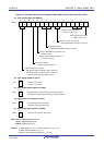
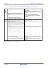
The TTmn (master) and TTmp (slave) bits are set to 1 at
the same time.
The TTmn and TTmp bits automatically return to 0
because they are trigger bits.
TEmn, TEmp = 0, and count operation stops.
The TCRmn and TCRmp registers hold count value and
stop.
The TOmp output is not initialized but holds current
status.
Operation
stop
The TOEmp bit of slave channel is cleared to 0 and value
is set to the TOmp bit.
The TOmp pin outputs the TOmp set level.
To hold the TOmp pin output level
Clears the TOmp bit to 0 after the value to
be held is set to the port register.
When holding the TOmp pin output level is not
necessary
Setting not required.
The TOmp pin output level is held by port function.
TAU
stop
The TAUmEN bit of the PER0 register is cleared to 0.
Power-off status
All circuits are initialized and SFR of each channel is
also initialized.
(The TOmp bit is cleared to 0 and the TOmp pin is set
to port mode.)
Remark m: Unit number (m = 0), n: Channel number (n = 0, 2, 4, 6)
p: Slave channel number (n < p ≤ 7)
However, timer output pin (TOmp) : p = 1, 3 to 7
Operation is resumed.