


RL78/G1A CHAPTER 5 CLOCK GENERATOR
R01UH0305EJ0200 Rev.2.00 167
Jul 04, 2013
5.6.3 Example of setting XT1 oscillation clock
After a reset release, the CPU/peripheral hardware clock (fCLK) always starts operating with the high-speed on-chip
oscillator clock. To subsequently change the clock to the XT1 oscillation clock, set the oscillator and start oscillation by
using the subsystem clock supply mode control register (OSMC), clock operation mode control register (CMC), and clock
operation status control register (CSC), set the XT1 oscillation clock to f
CLK by using the system clock control register
(CKC).
[Register settings] Set the register in the order of <1> to <5> below.
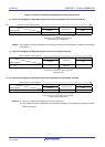
<1> To run only the real-time clock and 12-bit interval timer on the subsystem clock (ultra-low current consumption)
when in the STOP mode or sub-HALT mode, set the RTCLPC bit to 1.
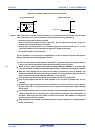
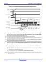
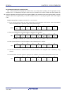
7 6 5 4 3 2 1 0
OSMC
RTCLPC
0/1
0
0
WUTMMCK0
0
0
0
0
0
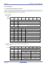
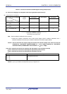
<2> Set (1) the OSCSELS bit of the CMC register to operate the XT1 oscillator.
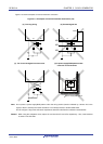
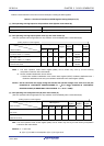
7 6 5 4 3 2 1 0
CMC
EXCLK
0
OSCSEL
0
EXCLKS
0
OSCSELS
1
0
AMPHS1
0/1
AMPHS0
0/1
AMPH
0
AMPHS0 and AMPHS1 bits: These bits are used to specify the oscillation mode of the XT1 oscillator.
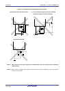
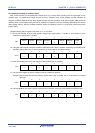
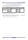
<3> Clear (0) the XTSTOP bit of the CSC register to start oscillating the XT1 oscillator.
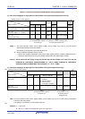
7 6 5 4 3 2 1 0
CSC
MSTOP
1
XTSTOP
0
0
0
0
0
0
HIOSTOP
0
<4> Use the timer function or another function to wait for oscillation of the subsystem clock to stabilize by using
software.
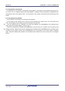
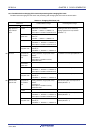
<5> Use the CSS bit of the CKC register to specify the XT1 oscillation clock as the CPU/peripheral hardware clock.
7 6 5 4 3 2 1 0
CKC
CLS
0
CSS
1
MCS
0
MCM0
0
0
0
0
0
<R>