


RL78/G1A CHAPTER 18 STANDBY FUNCTION
CHAPTER 18 STANDBY FUNCTION
18.1 Standby Function
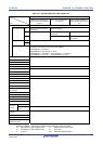
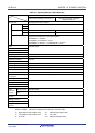
The standby function reduces the operating current of the system, and the following three modes are available.
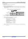
(1) HALT mode
HALT instruction execution sets the HALT mode. In the HALT mode, the CPU operation clock is stopped. If the high-
speed system clock oscillator, high-speed on-chip oscillator, or subsystem clock oscillator is operating before the
HALT mode is set, oscillation of each clock continues. In this mode, the operating current is not decreased as much
as in the STOP mode, but the HALT mode is effective for restarting operation immediately upon interrupt request
generation and carrying out intermittent operations frequently.
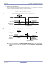
(2) STOP mode
STOP instruction execution sets the STOP mode. In the STOP mode, the high-speed system clock oscillator and
high-speed on-chip oscillator stop, stopping the whole system, thereby considerably reducing the CPU operating
current.
Because this mode can be cleared by an interrupt request, it enables intermittent operations to be carried out.
However, because a wait time is required to secure the oscillation stabilization time after the STOP mode is released
when the X1 clock is selected, select the HALT mode if it is necessary to start processing immediately upon interrupt
request generation.
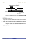
(3) SNOOZE mode
In the case of CSIp or UARTq data reception and an A/D conversion request by the timer trigger signal (the interrupt
request signal (INTRTC/INTIT)), the STOP mode is exited, the CSIp or UARTq data is received without operating the
CPU, and A/D conversion is performed. This can only be specified when the high-speed on-chip oscillator is selected
for the CPU/peripheral hardware clock (f
CLK).
In either of these two modes, all the contents of registers, flags and data memory just before the standby mode is set
are held. The I/O port output latches and output buffer statuses are also held.
Cautions 1. The STOP mode can be used only when the CPU is operating on the main system clock. Do not
set to the STOP mode while the CPU operates with the subsystem clock. The HALT mode can be
used when the CPU is operating on either the main system clock or the subsystem clock.
2. When shifting to the STOP mode, be sure to stop the peripheral hardware operation operating
with main system clock before executing STOP instruction (except SNOOZE mode setting unit).
3. When using CSIp, UARTq, or the A/D converter in the SNOOZE mode, set up serial standby
control register m (SSCm) and A/D converter mode register 2 (ADM2) before switching to the
STOP mode. For details, see 12.3 Registers Controlling Serial Array Unit and 11.3 Registers
Used in A/D Converter.
4. The following sequence is recommended for power consumption reduction of the A/D converter
when the standby function is used: First clear bit 7 (ADCS) and bit 0 (ADCE) of A/D converter
mode register 0 (ADM0) to 0 to stop the A/D conversion operation, and then execute the STOP
instruction.
5. It can be selected by the option byte whether the low-speed on-chip oscillator continues
oscillating or stops in the HALT or STOP mode. For details, see CHAPTER 24 OPTION BYTE.
Remark p = 00; q = 0; m = 0
R01UH0305EJ0200 Rev.2.00 726
Jul 04, 2013