


RL78/G1A CHAPTER 22 SAFETY FUNCTIONS
22.3.2 CRC operation function (general-purpose CRC)
In order to guarantee safety during operation, the IEC61508 standard mandates the checking of data even while the
CPU is operating.
In the RL78/G1A, a general CRC operation can be executed as a peripheral function while the CPU is operating. The
general CRC can be used for checking various data in addition to the code flash memory area. The data to be checked
can be specified by using software (a user-created program). CRC calculation function in the HALT mode can be used
only during the DMA transmission.
The general CRC operation can be executed in the main system clock operation mode as well as the subsystem clock
operation mode.
The CRC generator polynomial used is “X
16
+ X
12
+ X
5
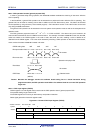
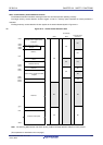
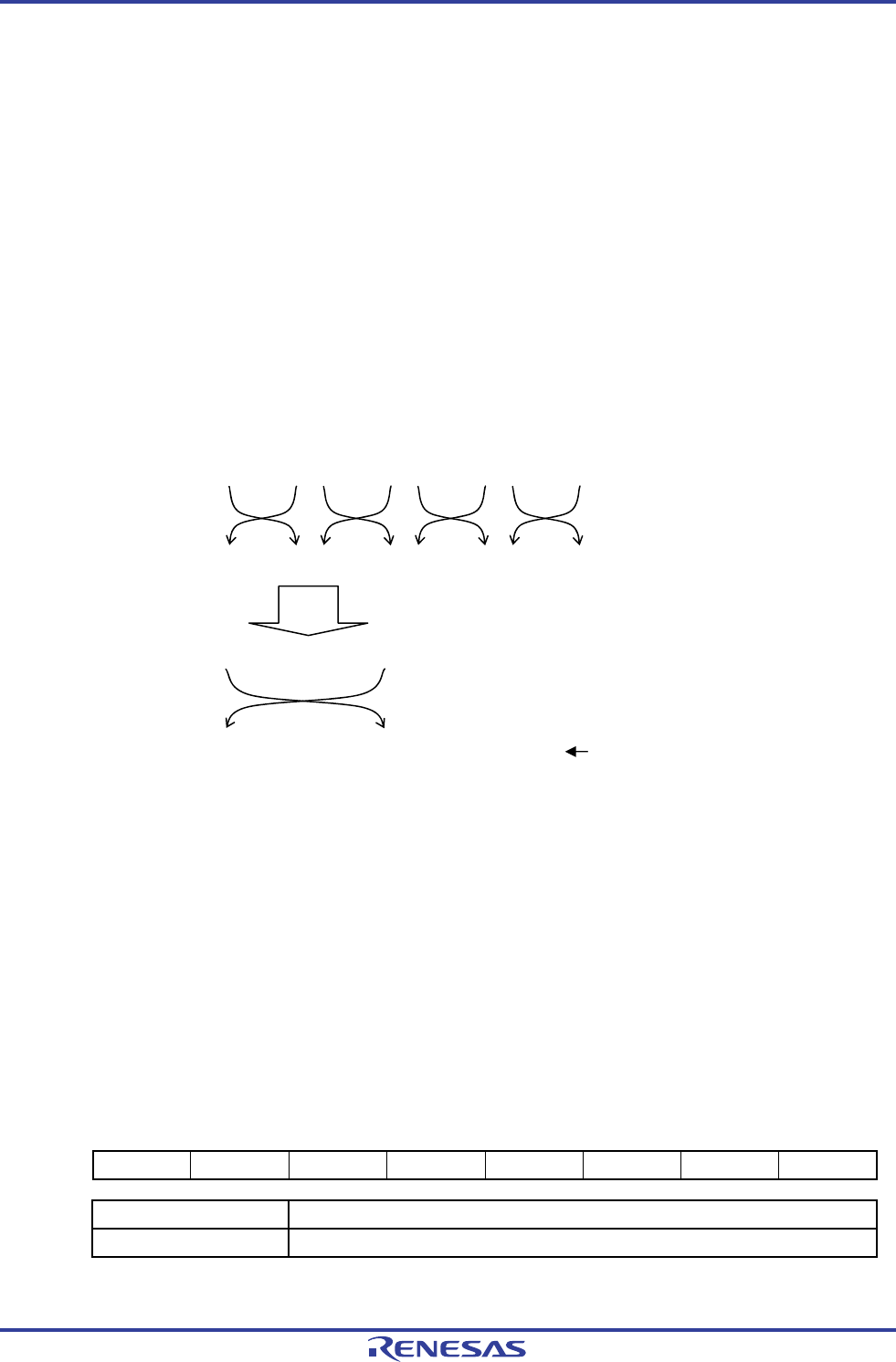
+ 1” of CRC-16-CCITT. The data to be input is inverted in bit
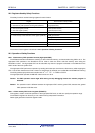
order and then calculated to allow for LSB-first communication. For example, if the data 12345678H is sent from the LSB,
values are written to the CRCIN register in the order of 78H, 56H, 34H, and 12H, enabling a value of 08F6H to be
obtained from the CRCD register. This is the result obtained by executing a CRC operation on the bit rows shown below,
which consist of the data 12345678H inverted in bit order.
CRCIN setting data 78H 56H 34H 12H
Bit representation data 0111 1000 0101 0110 0011 0100 0001 0010
Bit reverse
Bit reverse data 0001 1110 0110 1010 0010 1100 0100 1000
Bit reverse
Operation with polynomial
Result data 0110 1111 0001 0000
CRCD data 0000 1000 1111 0110 Obtained result
(08F6H)
Caution Because the debugger rewrites the software break setting line to a break instruction during
program execution, the CRC operation result differs if a software break is set in the CRC operation
target area.
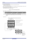
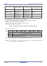
22.3.2.1 CRC input register (CRCIN)
CRCIN register is an 8-bit register that is used to set the CRC operation data of general-purpose CRC.
The possible setting range is 00H to FFH.
The CRCIN register can be set by an 8-bit memory manipulation instruction.
Reset signal generation clears this register to 00H.
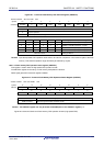
Figure 22-4. Format of CRC Input Register (CRCIN)
Address: FFFACH After reset: 00H R/W
Symbol 7 6 5 4 3 2 1 0
CRCIN
Bits 7 to 0 Function
00H to FFH Data input.
R01UH0305EJ0200 Rev.2.00 776
Jul 04, 2013