


RL78/G1A CHAPTER 20 POWER-ON-RESET CIRCUIT
CHAPTER 20 POWER-ON-RESET CIRCUIT
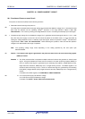
20.1 Functions of Power-on-reset Circuit
The power-on-reset circuit (POR) has the following functions.
• Generates internal reset signal at power on.
<R>
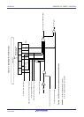
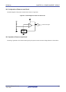
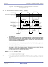
The reset signal is released when the supply voltage (V
DD) exceeds the detection voltage (VPOR). Note that the reset
state must be retained until the operating voltage
Note
becomes in the range defined in 29.4 or 30.4 AC
Characteristics. This is done by utilizing the voltage detection circuit or controlling the externally input reset signal.
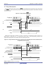
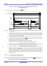
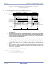
• Compares supply voltage (V
DD) and detection voltage (VPDR), generates internal reset signal when VDD < VPDR. Note
that, after the power supply is turned off, this LSI should be placed in the STOP mode, or in the reset state by
utilizing the voltage detection circuit or externally input reset signal, before the operation voltage
Note
falls below the
range defined in 29.4 or 30.4 AC Characteristics. When restarting the operation, make sure that the operation
voltage
Note
has returned within the range of operation.
<R>
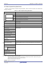
Note The operating voltage range varies depending on the setting specified by the user option byte
000C2H/010C2H.
Caution If an internal reset signal is generated in the power-on-reset circuit, the reset control flag register
(RESF) is cleared.
<R>
Remarks 1. The RL78 microcontroller incorporates multiple hardware functions that generate an internal reset
signal. A flag that indicates the reset source is located in the reset control flag register (RESF) for
when an internal reset signal is generated by the watchdog timer (WDT), voltage-detector (LVD),
illegal instruction execution, RAM parity error, or illegal-memory access. The RESF register is not
cleared to 00H and the flag is set to 1 when an internal reset signal is generated by the watchdog
timer (WDT), voltage-detector (LVD), illegal instruction execution, RAM parity error, or illegal-memory
access.
For details of the RESF register, see CHAPTER 19 RESET FUNCTION.
<R>
2. V
POR: POR power supply rise detection voltage
V
PDR: POR power supply fall detection voltage
For details, see 29.6.3 or 30.6.3 POR circuit characteristics.
R01UH0305EJ0200 Rev.2.00 749
Jul 04, 2013