


RL78/G1A CHAPTER 5 CLOCK GENERATOR
R01UH0305EJ0200 Rev.2.00 166
Jul 04, 2013
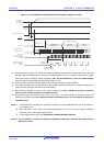
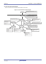
5.6.2 Example of setting X1 oscillation clock
After a reset release, the CPU/peripheral hardware clock (fCLK) always starts operating with the high-speed on-chip
oscillator clock. To subsequently change the clock to the X1 oscillation clock, set the oscillator and start oscillation by
using the oscillation stabilization time select register (OSTS) and clock operation mode control register (CMC) and clock
operation status control register (CSC) and wait for oscillation to stabilize by using the oscillation stabilization time counter
status register (OSTC). After the oscillation stabilizes, set the X1 oscillation clock to f
CLK by using the system clock control
register (CKC).
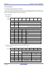
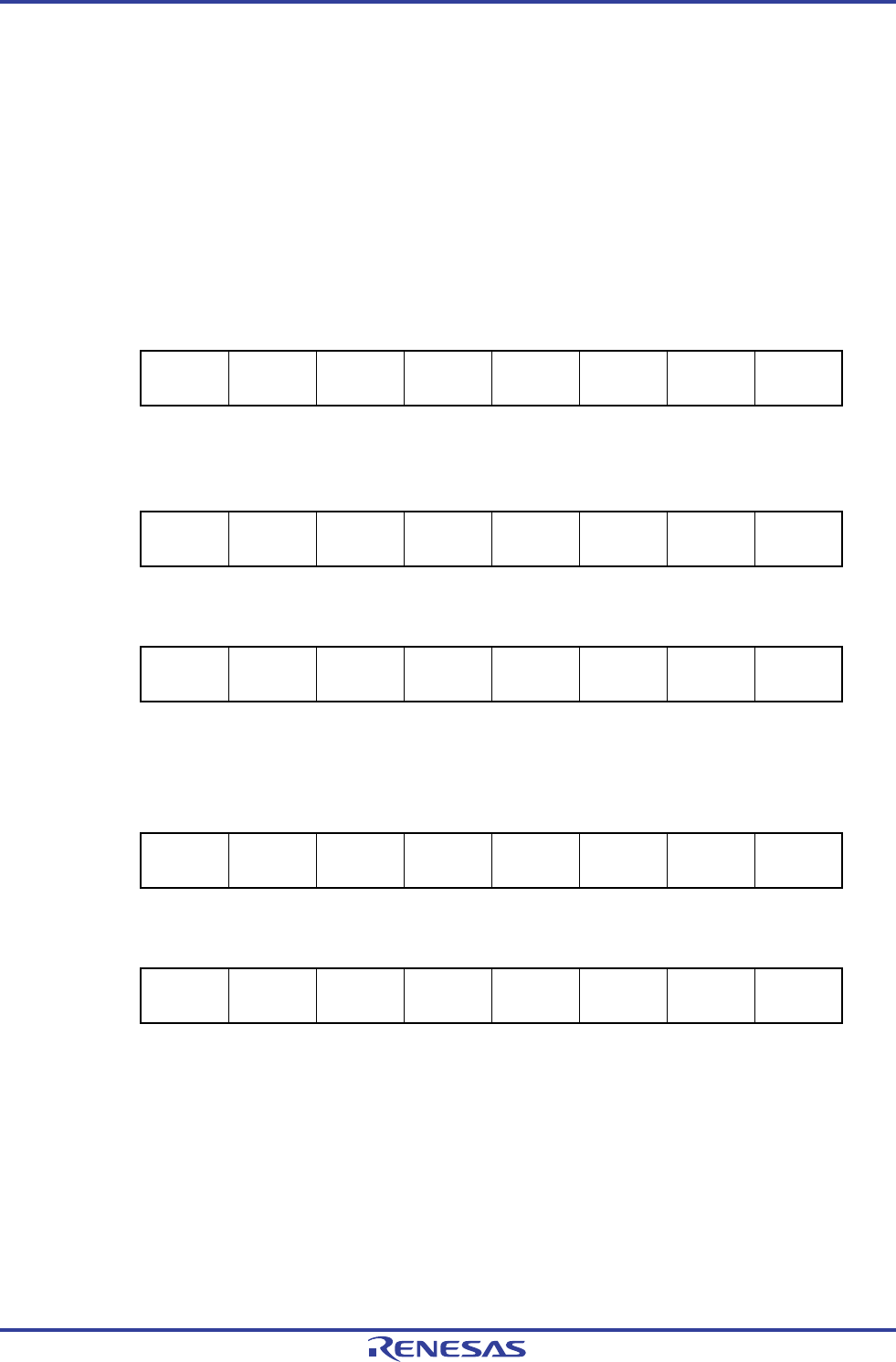
[Register settings] Set the register in the order of <1> to <5> below.
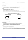
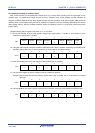
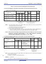
<1> Set (1) the OSCSEL bit of the CMC register, except for the cases where f
X > 10 MHz, in such cases set (1) the
AMPH bit, to operate the X1 oscillator.
7 6 5 4 3 2 1 0
CMC
EXCLK
0
OSCSEL
1
EXCLKS
0
OSCSELS
0
0
AMPHS1
0
AMPHS0
0
AMPH
0/1
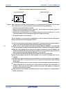
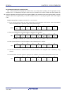
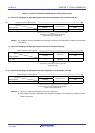
<2> Using the OSTS register, select the oscillation stabilization time of the X1 oscillator at releasing of the STOP mode.
Example: Setting values when a wait of at least 102
μ
s is set based on a 10 MHz resonator.
7 6 5 4 3 2 1 0
OSTS
0
0
0
0
0
OSTS2
0
OSTS1
1
OSTS0
0
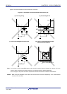
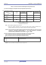
<3> Clear (0) the MSTOP bit of the CSC register to start oscillating the X1 oscillator.
7 6 5 4 3 2 1 0
CSC
MSTOP
0
XTSTOP
1
0
0
0
0
0
HIOSTOP
0
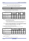
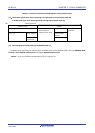
<4> Use the OSTC register to wait for oscillation of the X1 oscillator to stabilize.
Example: Wait until the bits reach the following values when a wait of at least 102
μ
s is set based on a 10 MHz
resonator.
7 6 5 4 3 2 1 0
OSTC
MOST8
1
MOST9
1
MOST10
1
MOST11
0
MOST13
0
MOST15
0
MOST17
0
MOST18
0
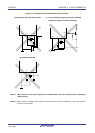
<5> Use the MCM0 bit of the CKC register to specify the X1 oscillation clock as the CPU/peripheral hardware clock.
7 6 5 4 3 2 1 0
CKC
CLS
0
CSS
0
MCS
0
MCM0
1
0
0
0
0