


RL78/G1A CHAPTER 6 TIMER ARRAY UNIT
R01UH0305EJ0200 Rev.2.00 289
Jul 04, 2013
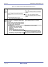
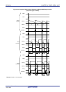
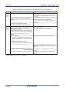
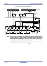
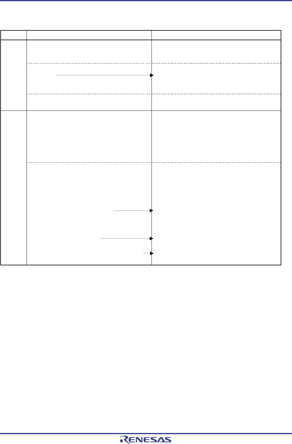
Figure 6-79. Operation Procedure When Multiple PWM Output Function Is Used (1/2)
Software Operation Hardware Status
Power-off status
(Clock supply is stopped and writing to each register is
disabled.)
Sets the TAUmEN bit of peripheral enable register 0
(PER0) to 1.
Power-on status. Each channel stops operating.
(Clock supply is started and writing to each register is
enabled.)
TAU
default
setting
Sets timer clock select register m (TPSm).
Determines clock frequencies of CKm0 and CKm1.
Sets timer mode registers mn, mp, 0q (TMRmn, TMRmp,
TMRmq) of each channel to be used (determines
operation mode of channels).
An interval (period) value is set to timer data register mn
(TDRmn) of the master channel, and a duty factor is set
to the TDRmp and TDRmq registers of the slave
channels.
Channel stops operating.
(Clock is supplied and some power is consumed.)
Channel
default
setting
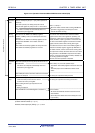
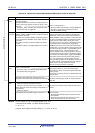
Sets slave channels.
The TOMmp and TOMmq bits of timer output mode
register m (TOMm) are set to 1 (slave channel output
mode).
Clears the TOLmp and TOLmq bits to 0.
Sets the TOmp and TOmq bits and determines default
level of the TOmp and TOmq outputs.
Sets the TOEmp and TOEmq bits to 1 and enables
operation of TOmp and TOmq.
Clears the port register and port mode register to 0.
The TOmp and TOmq pins go into Hi-Z output state.
The TOmp and TOmq default setting levels are output
when the port mode register is in output mode and the port
register is 0.
TOmp and TOmq do not change because channels stop
operating.
The TOmp and TOmq pins output the TOmp and TOmq
set levels.
(Note and Remark are listed on the next page.)