


RL78/G1A CHAPTER 4 PORT FUNCTIONS
R01UH0305EJ0200 Rev.2.00 98
Jul 04, 2013
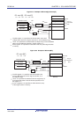
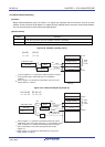
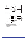
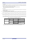
4.2.1 Port 0
Port 0 is an I/O port with an output latch. Port 0 can be set to the input mode or output mode in 1-bit units using port
mode register 0 (PM0). When the P00 to P06 pins are used as an input port, use of an on-chip pull-up resistor can be
specified in 1-bit units by pull-up resistor option register 0 (PU0).
Input to the P00, P01, P03 and P04 pins can be specified through a normal input buffer or a TTL input buffer in 1-bit
units using port input mode register 0 (PIM0).
Output from the P02 to P04 pins can be specified as N-ch open-drain output (V
DD tolerance
Note 1
/EVDD tolerance
Note 2
) in 1-
bit units using port output mode register 0 (POM0).
The P02 and P03 pins can be specified as digital input/output or analog input in 1-bit units, using port mode control
register 0 (PMC0).
This port can also be used for timer I/O, A/D converter analog input, serial interface data I/O, clock I/O, and key
interrupt input.
When reset signal is generated, the following configuration will be set.
· P00, P01 and P04 to P06 pins ··· Input mode
· P02 and P03 pins ··· Analog input
Notes 1. For 25- to 48-pin products
2. For 64-pin products
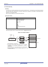
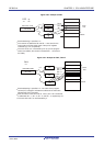
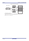
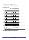
4.2.2 Port 1
Port 1 is an I/O port with an output latch. Port 1 can be set to the input mode or output mode in 1-bit units using port
mode register 1 (PM1). When the P10 to P16 pins are used as an input port, use of an on-chip pull-up resistor can be
specified in 1-bit units by pull-up resistor option register 1 (PU1).
Input to the P10, P11, and P14 to P16 pins can be specified through a normal input buffer or a TTL input buffer in 1-bit
units using port input mode register 1 (PIM1).
Output from the P10 to P15 pins can be specified as N-ch open-drain output (V
DD tolerance
Note 1
/EVDD tolerance
Note 2
) in 1-
bit units using port output mode register 1 (POM1).
The P10 to P15 pins can be specified as digital input/output or analog input in 1-bit units, using port mode control
register 1 (PMC1).
This port can also be used for A/D converter analog input, serial interface data I/O, clock I/O, programming UART I/O,
timer I/O, and external interrupt request input.
When reset signal is generated, the following configuration will be set.
· P10 to P15 pins ··· Analog input
· P16 pin ··· Input mode
Notes 1. For 25- to 48-pin products
2. For 64-pin products
<R>
<R>