


RL78/G1A CHAPTER 25 FLASH MEMORY
25.4.2 Flash memory programming mode
To rewrite the contents of the code flash memory through serial programming, specify the flash memory programming
mode. To enter the mode, set as follows.
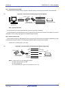
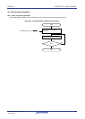
<Serial programming using the dedicated flash memory programmer>
Connect the RL78 microcontroller to a dedicated flash memory programmer. Communication from the dedicated
flash memory programmer is performed to automatically switch to the flash memory programming mode.
<Serial programming using an external device (UART communication)>
<R>
Set the TOOL0 pin to the low level, and then cancel the reset (see Table 25-4). After that, enter flash memory
programming mode according to the procedures <1> to <4> shown in Figure 25-7. For details, refer to the RL78
Microcontrollers (RL78 Protocol A) Programmer Edition Application Note (R01AN0815).
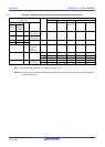
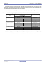
Table 25-4. Relationship Between TOOL0 Pin and Operation Mode After Reset Release
TOOL0 Operation Mode
EVDD0 Normal operation mode
0 V Flash memory programming mode
<R>
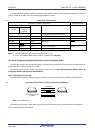
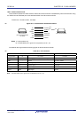
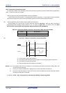
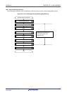
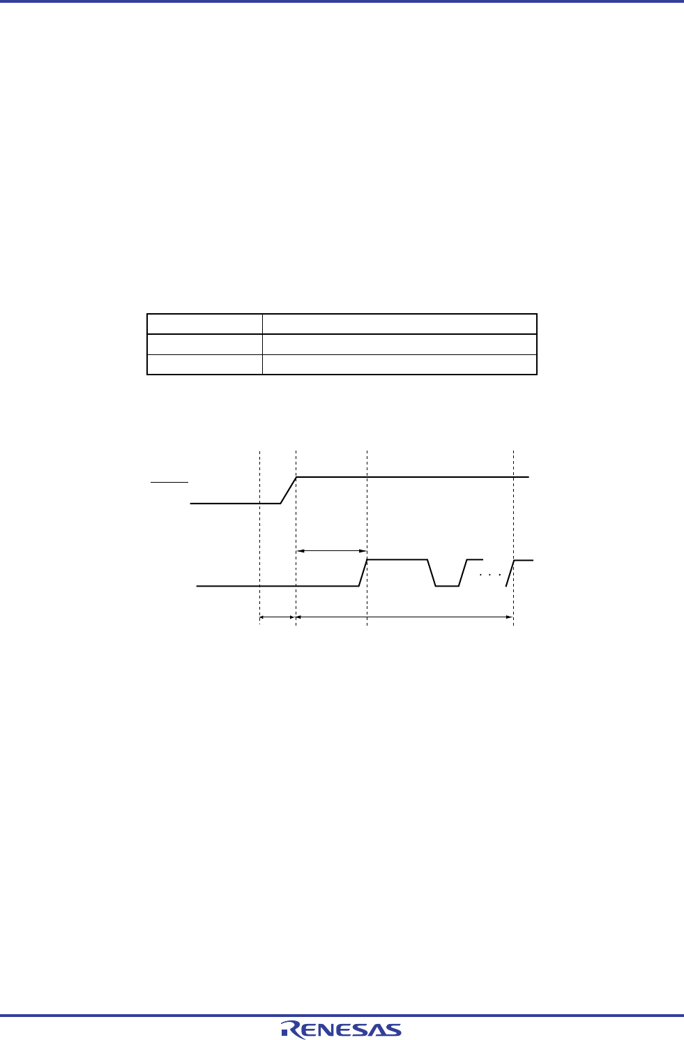
Figure 25-7. Setting of Flash Memory Programming Mode
RESET
TOOL0
<1>
<2>
<3>
t
SUINIT
723 μs + t
HD
processing time
t
SU
<4>
00H is received
(TOOLRxD and TOOLTxD mode)
<1> The low level is input to the TOOL0 pin.
<2> The external reset ends (POR and LVD reset must end before the external reset ends.).
<3> The TOOL0 pin is set to the high level.
<4> Baud rate setting by UART reception is completed.
Remark t
SUINIT: The segment shows that it is necessary to finish specifying the initial communication settings within 100
ms from when the resets end.
t
SU: How long from when the TOOL0 pin is placed at the low level until an external reset ends
t
HD: How long to keep the TOOL0 pin at the low level from when the external and internal resets end (the flash
firmware processing time is excluded)
For details, see 29.9 or 30.9 Timing Specs for Switching Flash Memory Programming Modes.
R01UH0305EJ0200 Rev.2.00 810
Jul 04, 2013