


RL78/G1A CHAPTER 12 SERIAL ARRAY UNIT
R01UH0305EJ0200 Rev.2.00 404
Jul 04, 2013
12.2 Configuration of Serial Array Unit
The serial array unit includes the following hardware.
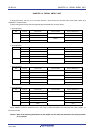
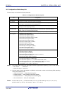
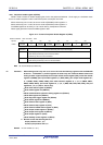
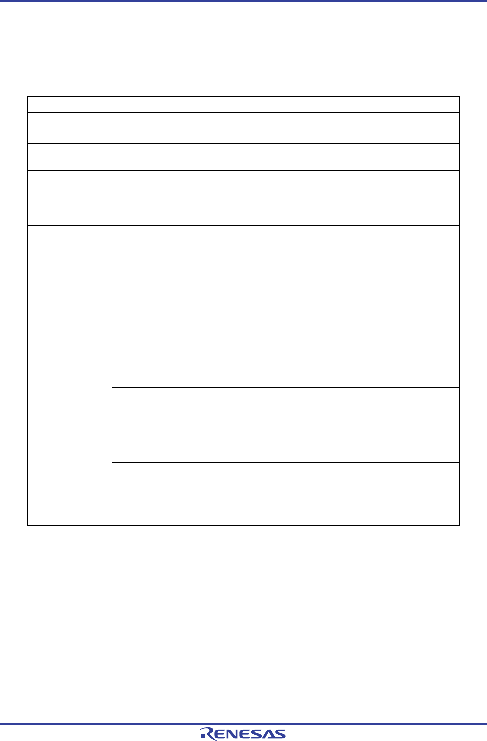
Table 12-1. Configuration of Serial Array Unit
Item Configuration
Shift register 8 bits or 9 bits
Note 1
Buffer register Lower 8 bits or 9 bits of serial data register mn (SDRmn)
Notes 1, 2
Serial clock I/O
SCK00, SCK01, SCK10, SCK11, SCK20, SCK21 pins (for 3-wire serial I/O), SCL00, SCL01,
SCL10, SCL11, SCL20, SCL21 pins (for simplified I
2
C)
Serial data input
SI00, SI01, SI10, SI11, SI20, SI21 pins (for 3-wire serial I/O), R
XD0, RxD1 pins (for UART),
R
XD2 pin (for UART supporting LIN-bus)
Serial data output
SO00, SO01, SO10, SO11, SO20, SO21 pins (for 3-wire serial I/O), T
XD0, TxD1 pins (for
UART), T
XD2 pin (for UART supporting LIN-bus)
Serial data I/O
SDA00, SDA01, SDA10, SDA11, SDA20, SDA21 pins (for simplified I
2
C)
<Registers of unit setting block>
• Peripheral enable register 0 (PER0)
• Serial clock select register m (SPSm)
• Serial channel enable status register m (SEm)
• Serial channel start register m (SSm)
• Serial channel stop register m (STm)
• Serial output enable register m (SOEm)
• Serial output register m (SOm)
• Serial output level register m (SOLm)
• Serial standby control register m (SSCm)
• Input switch control register (ISC)
• Noise filter enable register 0 (NFEN0)
<Registers of each channel>
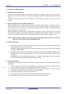
• Serial data register mn (SDRmn)
• Serial mode register mn (SMRmn)
• Serial communication operation setting register mn (SCRmn)
• Serial status register mn (SSRmn)
• Serial flag clear trigger register mn (SIRmn)
Control registers
• Port input mode registers 0, 1 (PIM0, PIM1)
• Port output mode registers 0, 1, 5, 7 (POM0, POM1, POM5, POM7)
• Port mode control registers 0, 1, 3, 5, 7 (PMC0, PMC1, PMC3, PMC5, PMC7)
• Port mode registers 0, 1, 3, 5, 7 (PM0, PM1, PM3, PM5, PM7)
• Port registers 0, 1, 3, 5, 7 (P0, P1, P3, P5, P7)
Notes 1. The number of bits used as the shift register and buffer register differs depending on the unit and channel.
• mn = 00, 01: lower 9 bits
• Other than above: lower 8 bits
2. The lower 8 bits of serial data register mn (SDRmn) can be read or written as the following SFR, depending
on the communication mode.
• CSIp communication … SIOp (CSIp data register)
• UARTq reception … RXDq (UARTq receive data register)
• UARTq transmission … TXDq (UARTq transmit data register)
• IICr communication … SIOr (IICr data register)
Remark m: Unit number (m = 0, 1), n: Channel number (n = 0 to 3), p: CSI number (p = 00, 01, 10, 11, 20, 21),
q: UART number (q = 0 to 2), r: IIC number (r = 00, 01, 10, 11, 20, 21)