


RL78/G1A CHAPTER 16 INTERRUPT FUNCTIONS
16.3.1 Interrupt request flag registers (IF0L, IF0H, IF1L, IF1H, IF2L, IF2H)
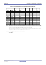
The interrupt request flags are set to 1 when the corresponding interrupt request is generated or an instruction is
executed. They are cleared to 0 when an instruction is executed upon acknowledgment of an interrupt request or upon
reset signal generation.
When an interrupt is acknowledged, the interrupt request flag is automatically cleared and then the interrupt routine is
entered.
The IF0L, IF0H, IF1L, IF1H, IF2L, and IF2H registers can be set by a 1-bit or 8-bit memory manipulation instruction.
When the IF0L and IF0H registers, the IF1L and IF1H registers, and the IF2L and IF2H registers are combined to form 16-
bit registers IF0, IF1, and IF2, they can be set by a 16-bit memory manipulation instruction.
Reset signal generation clears these registers to 00H.
Remark If an instruction that writes data to this register is executed, the number of instruction execution clocks
increases by 2 clocks.
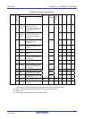
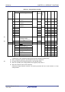
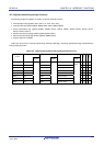
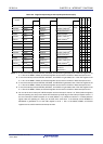
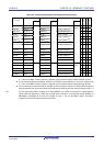
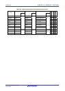
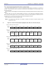
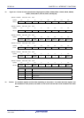
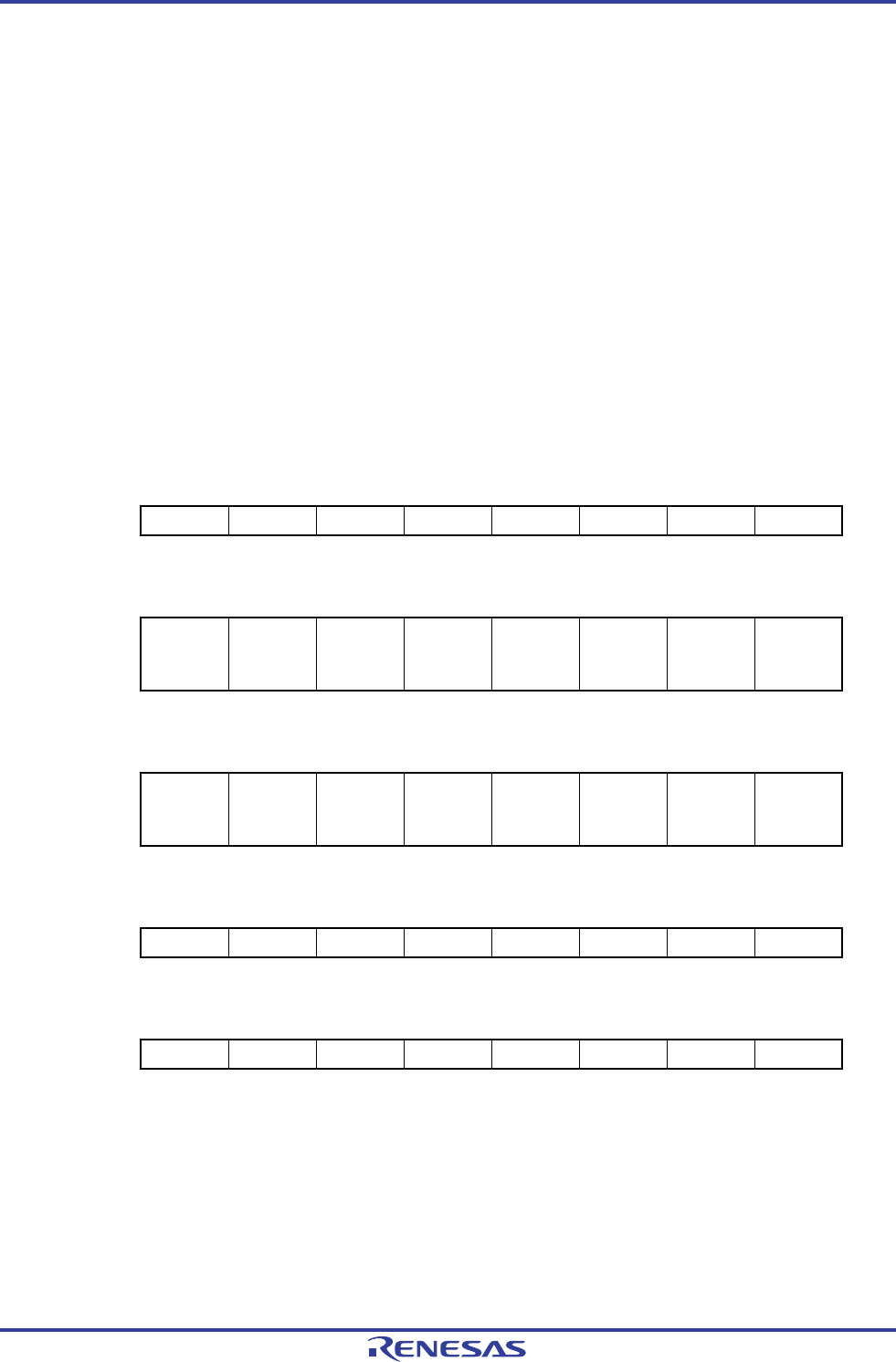
Figure 16-2. Format of Interrupt Request Flag Registers (IF0L, IF0H, IF1L, IF1H, IF2L, IF2H) (1/2)
<R>
Address: FFFE0H After reset: 00H R/W
Symbol <7> <6> <5> <4> <3> <2> <1> <0>
IF0L PIF5 PIF4 PIF3 PIF2 PIF1 PIF0 LVIIF WDTIIF
Address: FFFE1H After reset: 00H R/W
Symbol <7> <6> <5> <4> <3> <2> <1> <0>
IF0H
SREIF0
TMIF01H
SRIF0
CSIIF01
IICIF01
STIF0
CSIIF00
IICIF00
DMAIF1 DMAIF0
SREIF2
TMIF11H
SRIF2
CSIIF21
IICIF21
STIF2
CSIIF20
IICIF20
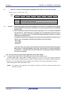
Address: FFFE2H After reset: 00H R/W
Symbol <7> <6> <5> <4> <3> <2> <1> <0>
IF1L TMIF03 TMIF02 TMIF01 TMIF00 IICAIF0
SREIF1
TMIF03H
SRIF1
CSIIF11
IICIF11
STIF1
CSIIF10
IICIF10
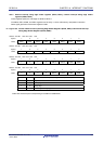
Address: FFFE3H After reset: 00H R/W
Symbol <7> 6 5 4 <3> <2> <1> <0>
IF1H TMIF04 0 0 0 KRIF ITIF RTCIF ADIF
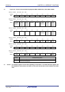
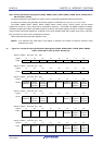
Address: FFFD0H After reset: 00H R/W
Symbol <7> <6> <5> <4> <3> <2> <1> <0>
IF2L PIF10 PIF9 PIF8 PIF7 PIF6 TMIF07 TMIF06 TMIF05
R01UH0305EJ0200 Rev.2.00 698
Jul 04, 2013