


RL78/G1A CHAPTER 6 TIMER ARRAY UNIT
R01UH0305EJ0200 Rev.2.00 276
Jul 04, 2013
6.9.2 Operation as PWM function
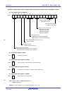
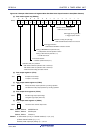
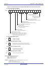
Two channels can be used as a set to generate a pulse of any period and duty factor.
The period and duty factor of the output pulse can be calculated by the following expressions.
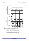
Pulse period = {Set value of TDRmn (master) + 1} × Count clock period
Duty factor [%] = {Set value of TDRmp (slave)}/{Set value of TDRmn (master) + 1} × 100
0% output: Set value of TDRmp (slave) = 0000H
100% output: Set value of TDRmp (slave) ≥ {Set value of TDRmn (master) + 1}
Remark The duty factor exceeds 100% if the set value of TDRmp (slave) > (set value of TDRmn (master) + 1), it
summarizes to 100% output.
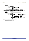
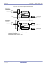
The master channel operates in the interval timer mode. If the channel start trigger bit (TSmn) of timer channel start
register m (TSm) is set to 1, an interrupt (INTTMmn) is output, the value set to timer data register mn (TDRmn) is loaded
to timer count register mn (TCRmn), and the counter counts down in synchronization with the count clock. When the
counter reaches 0000H, INTTMmn is output, the value of the TDRmn register is loaded again to the TCRmn register, and
the counter counts down. This operation is repeated until the channel stop trigger bit (TTmn) of timer channel stop
register m (TTm) is set to 1.
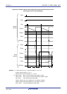
If two channels are used to output a PWM waveform, the period until the master channel counts down to 0000H is the
PWM output (TOmp) cycle.
The slave channel operates in one-count mode. By using INTTMmn from the master channel as a start trigger, the
TCRmp register loads the value of the TDRmp register and the counter counts down to 0000H. When the counter
reaches 0000H, it outputs INTTMmp and waits until the next start trigger (INTTMmn from the master channel) is generated.
If two channels are used to output a PWM waveform, the period until the slave channel counts down to 0000H is the
PWM output (TOmp) duty.
PWM output (TOmp) goes to the active level one clock after the master channel generates INTTMmn and goes to the
inactive level when the TCRmp register of the slave channel becomes 0000H.
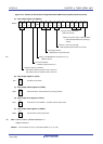
Caution To rewrite both timer data register mn (TDRmn) of the master channel and the TDRmp register of the
slave channel, a write access is necessary two times. The timing at which the values of the TDRmn
and TDRmp registers are loaded to the TCRmn and TCRmp registers is upon occurrence of INTTMmn
of the master channel. Thus, when rewriting is performed split before and after occurrence of
INTTMmn of the master channel, the TOmp pin cannot output the expected waveform. To rewrite both
the TDRmn register of the master and the TDRmp register of the slave, therefore, be sure to rewrite
both the registers immediately after INTTMmn is generated from the master channel.
Remark m: Unit number (m = 0), n: Channel number (n = 0, 2, 4, 6)
p: Slave channel number (n < p ≤ 7 )
However, timer output pin (TOmp) : p = 1, 3 to 7