


RL78/G1A CHAPTER 13 SERIAL INTERFACE IICA
13.3.5 IICA control register 01 (IICCTL01)
This register is used to set the operation mode of I
2
C and detect the statuses of the SCLA0 and SDAA0 pins.
The IICCTL01 register can be set by a 1-bit or 8-bit memory manipulation instruction. However, the CLD0 and DAD0
bits are read-only.
Set the IICCTL01 register, except the WUP0 bit, while operation of I
2
C is disabled (bit 7 (IICE0) of IICA control register
00 (IICCTL00) is 0).
Reset signal generation clears this register to 00H.
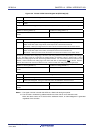
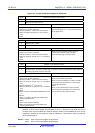
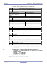
Figure 13-9. Format of IICA Control Register 01 (IICCTL01) (1/2)
Address: F0231H After reset: 00H R/W
Note 1
Symbol <7> 6 <5> <4> <3> <2> 1 <0>
IICCTL01 WUP0 0 CLD0 DAD0 SMC0 DFC0 0 PRS0
WUP0 Control of address match wakeup
0 Stops operation of address match wakeup function in STOP mode.
1 Enables operation of address match wakeup function in STOP mode.
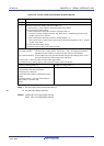
To shift to STOP mode when WUP0 = 1, execute the STOP instruction at least three clocks of fMCK after setting
(1) the WUP0 bit (see Figure 13-22 Flow When Setting WUP0 = 1).
Clear (0) the WUP0 bit after the address has matched or an extension code has been received. The
subsequent communication can be entered by the clearing (0) WUP0 bit. (The wait must be released and
transmit data must be written after the WUP0 bit has been cleared (0).)
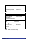
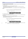
The interrupt timing when the address has matched or when an extension code has been received, while WUP0
= 1, is identical to the interrupt timing when WUP0 = 0. (A delay of the difference of sampling by the clock will
occur.) Furthermore, when WUP0 = 1, a stop condition interrupt is not generated even if the SPIE0 bit is set to
1.
When WUP0 = 0 is set by a source other than an interrupt from serial interface IICA, operation as the master
device cannot be performed until the subsequent start condition or stop condition is detected. Do not output a
start condition by setting (1) the STT0 bit, without waiting for the detection of the subsequent start condition or
stop condition.
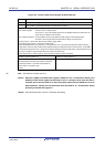
Condition for clearing (WUP0 = 0) Condition for setting (WUP0 = 1)
• Cleared by instruction (after address match or
extension code reception)
• Set by instruction (when the MSTS0, EXC0, and
COI0 bits are “0”, and the STD0 bit also “0”
(communication not entered))
Note 2
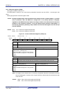
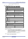
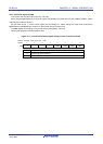
Notes 1. Bits 4 and 5 are read-only.
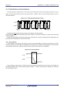
2. The status of the IICA status register 0 (IICS0) must be checked and the WUP0 bit must be set
during the period shown below.
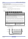
SCLA0
<1> <2>
SDAA0
A6 A5 A4 A3 A2 A1 A0
The maximum time from reading IICS0 to setting
WUP0 is the period from <1> to <2>.
Check the IICS0 operation status and set
WUP0 during this period.
R/W
R01UH0305EJ0200 Rev.2.00 583
Jul 04, 2013