


RL78/G1A CHAPTER 11 A/D CONVERTER
R01UH0305EJ0200 Rev.2.00 343
Jul 04, 2013
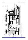
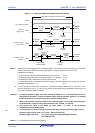
11.2 Configuration of A/D Converter
The A/D converter includes the following hardware.
(1) ANI0 to ANI12 and ANI16 to ANI30 pins
These are the analog input pins of the 28 channels of the A/D converter. They input analog signals to be converted
into digital signals. Pins other than the one selected as the analog input pin can be used as I/O port pins.
(2) Sample & hold circuit
The sample & hold circuit samples each of the analog input voltages sequentially sent from the input circuit, and
sends them to the A/D voltage comparator. This circuit also holds the sampled analog input voltage during A/D
conversion.
(3) A/D voltage comparator
This A/D voltage comparator compares output from the voltage tap of the comparison voltage generator with the
sampled voltage value.
If the analog input voltage is found to be greater than the reference voltage (1/2 AV
REF) as a result of the comparison,
the most significant bit (MSB) of the successive approximation register (SAR) is set. If the analog input voltage is less
than the reference voltage (1/2 AV
REF), the MSB bit of the SAR is reset.
After that, bit 10 of the SAR register is automatically set, and the next comparison is made. The voltage tap of the
comparison voltage generator is selected by the value of bit 11, to which the result has been already set.
Bit 11 = 0: (1/4 AV
REF)
Bit 11 = 1: (3/4 AVREF)
The voltage tap of the comparison voltage generator and the analog input voltage are compared and bit 10 of the
SAR register is manipulated according to the result of the comparison.
Analog input voltage ≥ Voltage tap of comparison voltage generator: Bit 10 = 1
Analog input voltage ≤ Voltage tap of comparison voltage generator: Bit 10 = 0
Comparison is continued like this to bit 0 of the SAR register.
When performing A/D conversion at a resolution of 8 bits, the comparison continues until bit 4 of the SAR register.
Remark AV
REF: The + side reference voltage of the A/D converter.
(This can be selected from AVREFP, the internal reference voltage (1.45 V), and AVDD.)
(4) Comparison voltage generator
The comparison voltage generator generates the comparison voltage input from an analog input pin.