


RL78/G1A CHAPTER 15 DMA CONTROLLER
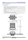
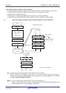
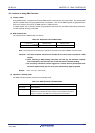
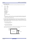
15.5.3 UART consecutive reception + ACK transmission
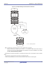
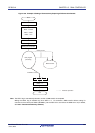
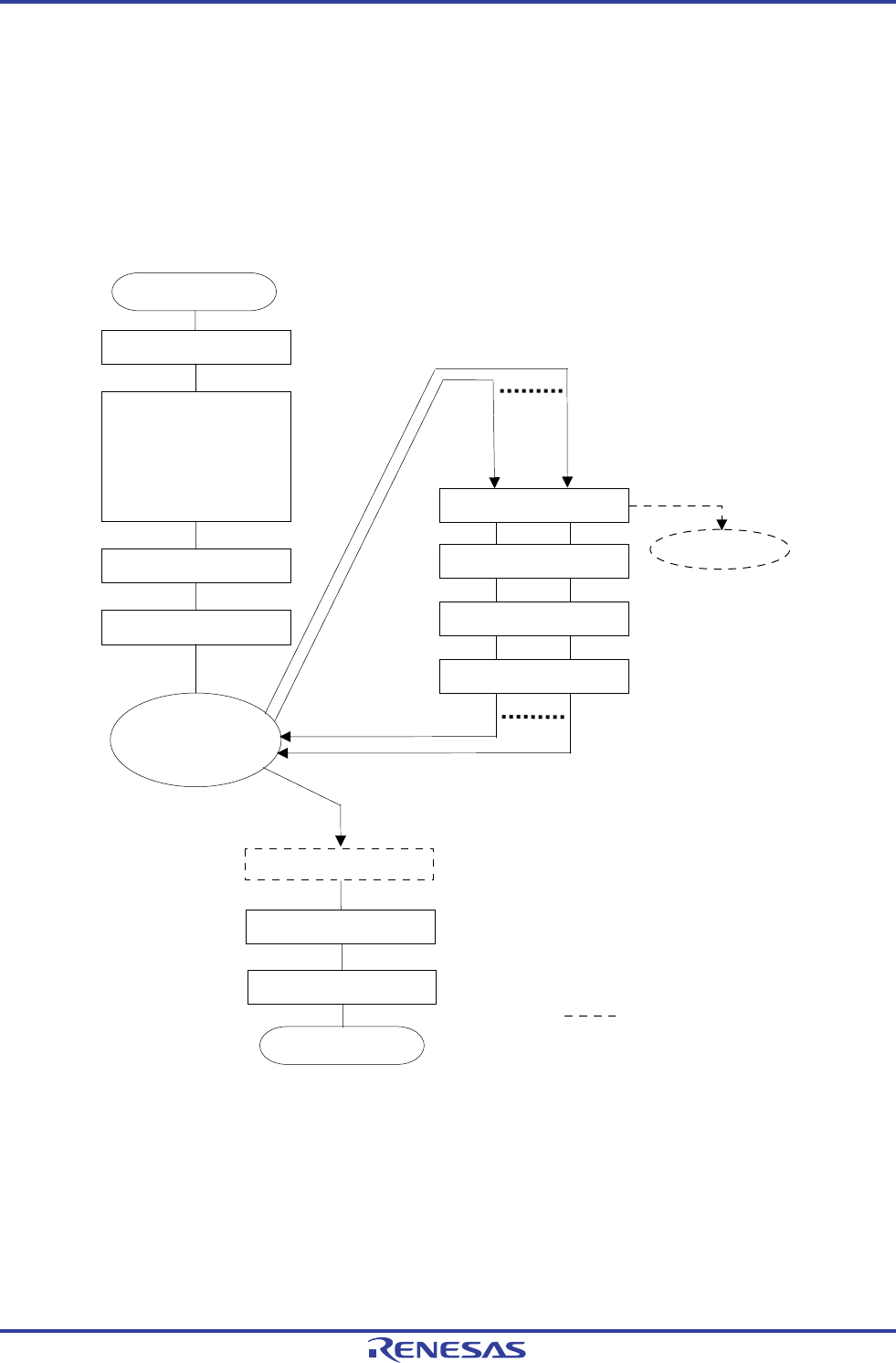
A flowchart illustrating an example of setting for UART consecutive reception + ACK transmission is shown below.
• Consecutively receives data from UART0 and outputs ACK to P10 on completion of reception.
• DMA channel 0 is used for DMA transfer.
• DMA start source: Software trigger (DMA transfer on occurrence of an interrupt is disabled.)
• Transfers FFF12H of UART receive data register 0 (RXD0) to 64 bytes of FFE00H to FFE3FH of RAM.
Figure 15-9. Example of Setting for UART Consecutive Reception + ACK Transmission
<R>
DEN0 = 1
DSA0 = 12H
DRA0 = FE00H
DBC0 = 0040H
DMC0 = 00H
DEN0 = 0
Note
Setting for UART reception
DST0 = 1
User program
processing
STG0 = 1
P10 = 1
P10 = 0
INTSR0 occurs.
INTDMA0
occurs.
DST0 = 0
RETI
Hardware operation
Start
End
RETI
INTSR0 interrupt routine
DMA0 transfer
DMA0 is started.
Note The DST0 flag is automatically cleared to 0 when a DMA transfer is completed.
Writing the DEN0 flag is enabled only when DST0 = 0. To terminate a DMA transfer without waiting for
occurrence of the interrupt of DMA0 (INTDMA0), set the DST0 bit to 0 and then the DEN0 bit to 0 (for details,
see 15.5.5 Forced termination by software).
Remark This is an example where a software trigger is used as a DMA start source.
If ACK is not transmitted and if only data is consecutively received from UART, the UART reception end
interrupt (INTSR0) can be used to start DMA for data reception.
R01UH0305EJ0200 Rev.2.00 681
Jul 04, 2013