


RL78/G1A CHAPTER 12 SERIAL ARRAY UNIT
R01UH0305EJ0200 Rev.2.00 422
Jul 04, 2013
12.3.9 Serial channel stop register m (STm)
The STm register is a trigger register that is used to enable stopping communication/count by each channel.
When 1 is written a bit of this register (STmn), the corresponding bit (SEmn) of serial channel enable status register m
(SEm) is cleared to 0 (operation is stopped). Because the STmn bit is a trigger bit, it is cleared immediately when SEmn =
0.
The STm register can set written by a 16-bit memory manipulation instruction.
The lower 8 bits of the STm register can be set with a 1-bit or 8-bit memory manipulation instruction with STmL.
Reset signal generation clears the STm register to 0000H.
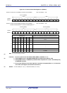
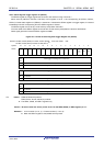
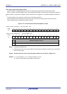
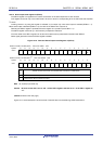
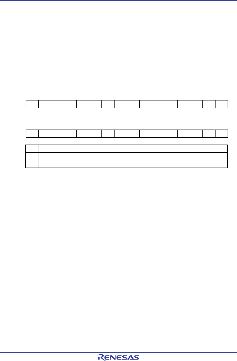
Figure 12-12. Format of Serial Channel Stop Register m (STm)
Address: F0124H, F0125H (ST0) After reset: 0000H R/W
Symbol 15 14 13 12 11 10 9 8 7 6 5 4 3 2 1 0
ST0 0 0 0 0 0 0 0 0 0 0 0 0 ST03 ST02 ST01 ST00
Address: F0164H, F0165H (ST1)
Note 1
After reset: 0000H R/W
Symbol 15 14 13 12 11 10 9 8 7 6 5 4 3 2 1 0
ST1 0 0 0 0 0 0 0 0 0 0 0 0 0 0 ST11 ST10
STmn Operation stop trigger of channel n
0 No trigger operation
1
Clears the SEmn bit to 0 and stops the communication operation
Note 2
.
Notes 1. 32, 48, 64-pin products only
2. Holding status value of the control register and shift register, the SCKmn and SOmn pins, and FEFmn,
PEFmn, OVFmn flags.
Caution Be sure to clear bits 15 to 4 of the ST0 register and bits 15 to 2 of the ST1 register to “0”.
Remarks 1. m: Unit number (m = 0, 1), n: Channel number (n = 0 to 3)
2. When the STm register is read, 0000H is always read.