


RL78/G1A CHAPTER 13 SERIAL INTERFACE IICA
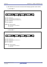
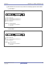
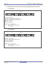
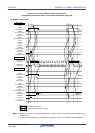
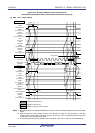
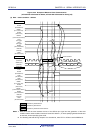
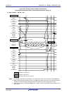
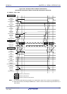
Figure 13-32. Example of Master to Slave Communication
(9-Clock Wait Is Selected for Master, 9-Clock Wait Is Selected for Slave) (3/4)
(3) Data ~ data ~ Stop condition
Master side
D
16
1
IICA0
STT0
(ST trigger)
SPT0
(SP trigger)
ACKD0
(ACK detection)
WTIM0
(8 or 9 clock wait)
ACKE0
(ACK control)
MSTS0
(communication status)
TRC0
(transmit/receive)
SCLA0 (bus)
(clock line)
WREL0
(wait cancellation)
INTIICA0
(interrupt)
SDAA0 (bus)
(data line)
D
16
2
D
16
3D
16
4D
16
5
D
16
0D
16
6
IICA0
STD0
(ST detection)
SPD0
(SP detection)
ACKD0
(ACK detection)
WTIM0
(8 or 9 clock wait)
ACKE0
(ACK control)
MSTS0
(communication status)
TRC0
(transmit/receive)
WREL0
(wait cancellation)
INTIICA0
(interrupt)
D
15
0
D
16
7
Bus line
Slave side
L
L
H
H
L
L
H
H
L
ACK
ACK
Note 1
Stop condition
<14>
<9>
Note 2
<8>
<12>
<7>
<11>
<15>
<10> <13>
Note 3
Note 3
: Wait state by master device
: Wait state by slave device
: Wait state by master and slave devices
Notes 1. Write data to IICA0, not setting the WREL0 bit, in order to cancel a wait state during transmission by a master
device.
2. Make sure that the time between the rise of the SCLA0 pin signal and the generation of the stop
condition after a stop condition has been issued is at least 4.0
μ
s when specifying standard mode and
at least 0.6
μ
s when specifying fast mode.
3. For releasing wait state during reception of a slave device, write “FFH” to IICA0 or set the WREL0 bit.
R01UH0305EJ0200 Rev.2.00 642
Jul 04, 2013