


RL78/G1A CHAPTER 4 PORT FUNCTIONS
R01UH0305EJ0200 Rev.2.00 99
Jul 04, 2013
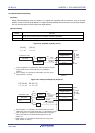
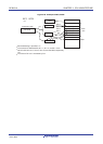
4.2.3 Port 2
Port 2 is an I/O port with an output latch. Port 2 can be set to the input mode or output mode in 1-bit units using port
mode register 2 (PM2).
This port can also be used for A/D converter analog input and reference voltage input (+ side and − side).
To use P20/ANI0 to P27/ANI7 as digital I/O pins, set them in the digital I/O mode by using the A/D port configuration
register (ADPC). Use these pins starting from the upper bit.
To use P20/ANI0 to P27/ANI7 as analog input pins, set them in the analog input mode by using the A/D port
configuration register (ADPC) and in the input mode by using the PM2 register. Use these pins starting from the lower bit.
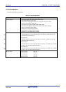
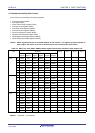
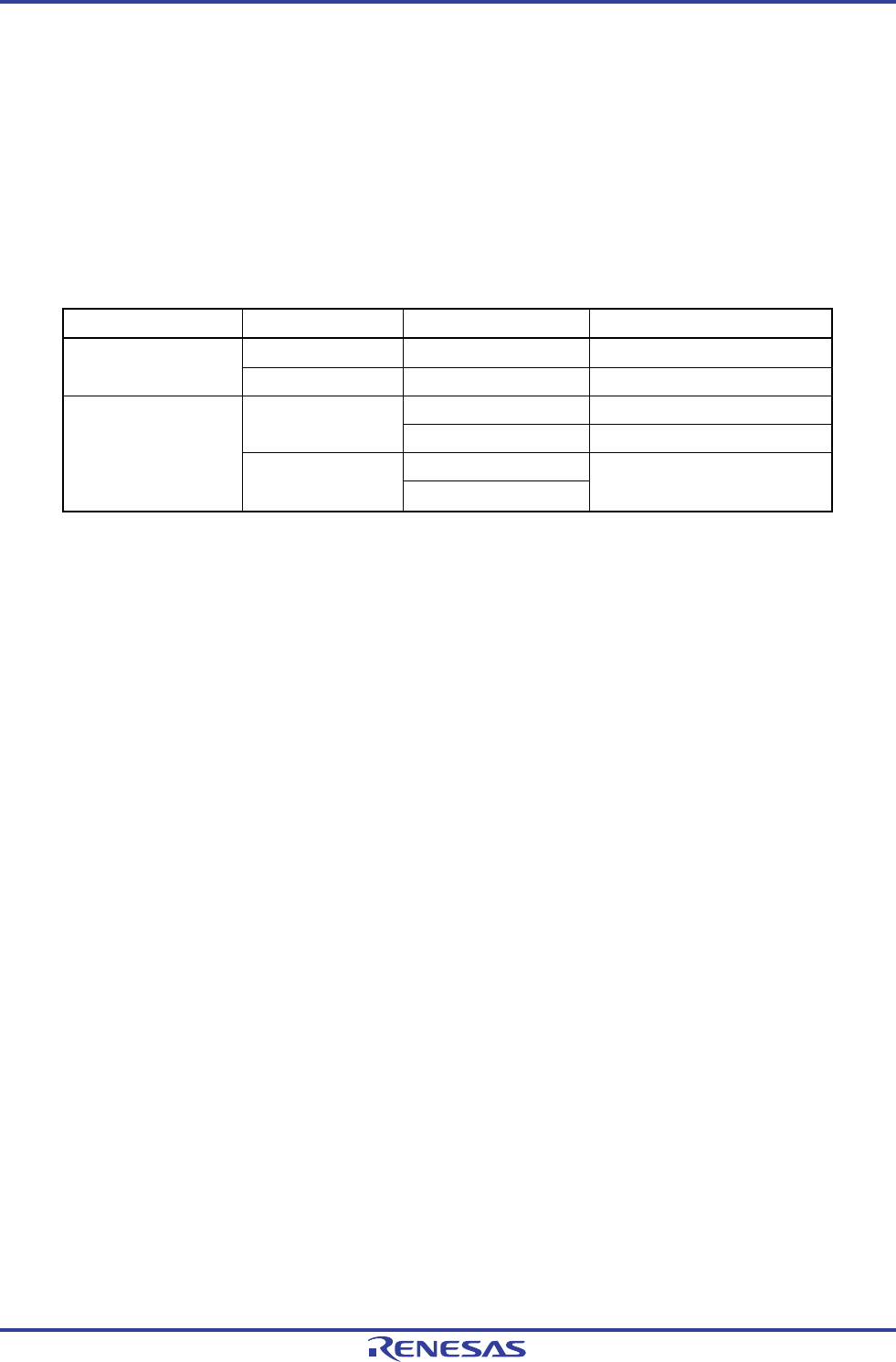
Table 4-2. Setting Functions of P20/ANI0 to P27/ANI7 Pins
ADPC Register PM2 Register ADS Register P20/ANI0 to P27/ANI7 Pins
Input mode
−
Digital input Digital I/O selection
Output mode
−
Digital output
Selects ANI. Analog input (to be converted) Input mode
Does not select ANI. Analog input (not to be converted)
Selects ANI.
Analog input selection
Output mode
Does not select ANI.
Setting prohibited
All P20/ANI0 to P27/ANI7 are set in the analog input mode when the reset signal is generated.
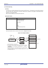
4.2.4 Port 3
Port 3 is an I/O port with an output latch. Port 3 can be set to the input mode or output mode in 1-bit units using port
mode register 3 (PM3). When the P30, P31 pins are used as an input port, use of an on-chip pull-up resistor can be
specified in 1-bit units by pull-up resistor option register 3 (PU3).
The P30 and P31 pins can be specified as digital input/output or analog input in 1-bit units, using port mode control
register 3 (PMC3).
This port can also be used for A/D converter analog input, external interrupt request input, real-time clock correction
clock output, serial interface data I/O, clock I/O, and timer I/O.
Reset signal generation sets P30, P31 to analog input.
<R>
<R>