


RL78/G1A CHAPTER 12 SERIAL ARRAY UNIT
R01UH0305EJ0200 Rev.2.00 540
Jul 04, 2013
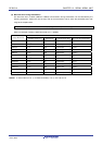
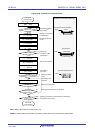
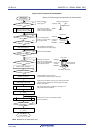
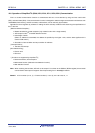
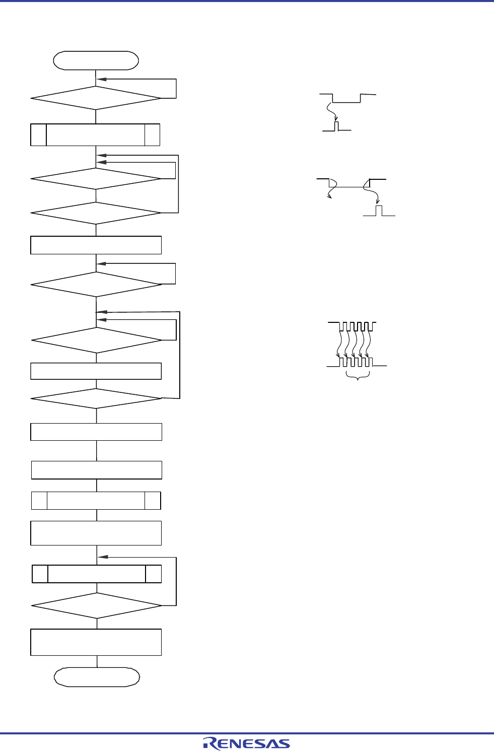
Figure 12-100. Flowchart for LIN Reception
INTTM07
No
Yes
INTP0
No
INTTM07
No
No
Yes
Ye s
N
o
Yes
Yes
No
Yes
No
Yes
Starting LIN
communication
Generate INTP0?
Starting in low-level width
measurement mode for TM07
Generate INTTM07?
11 bit lengths or more?
Changing TM07 to pulse
width measurement
Generate INTTM07?
Generate INTTM07?
Capture value cumulative
Completed 4 times?
Changing TM07 to low-level
width measurement
Calculate the baud rate
UART2 default setting
Starting UART2 reception
(1 → SS11)
Data reception
Completing all data
transmission?
Stop UART2 reception
(1 → ST11)
End of LIN
communication
Wait for wakeup
frame signal
Note
The low-level width of
RxD2 is measured using
TM07 and BF is detected.
If the detected pulse
width is 11 bits or more,
it is judged as BF.
Set up TM07 to measure the
interval between the falling edges.
Ignore the first INTTM07.
Measure the intervals
between five falling edges
of SF, and accumulate the
four captured values.
Change TM07 to low-level width
measurement to detect a Sync break field.
Divide the accumulated value by 8 to obtain the bit width.
Use this value to determine the setting values of SPS1,
SDR10, and SDR11.
Set up the initial setting of UART2 according to the
LIN communication conditions.
Receive the ID, data, and checksum fields
(if the ID matches).
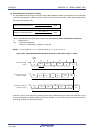
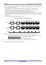
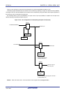
Status of LIN bus signal and operation of the hardware
Wakeup signal frame
RxD2 pin
RxD2 pin
RxD2 pin
Channel 7
of TAU0
Channel 7
of TAU0
Channel 7
Edge detection
Break field
Pulse width
measurement
Sync field
Pulse interval
measurement
Cumulative four times
Note Required in the sleep status only.