


RL78/G1A CHAPTER 5 CLOCK GENERATOR
R01UH0305EJ0200 Rev.2.00 172
Jul 04, 2013
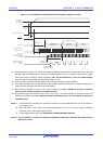
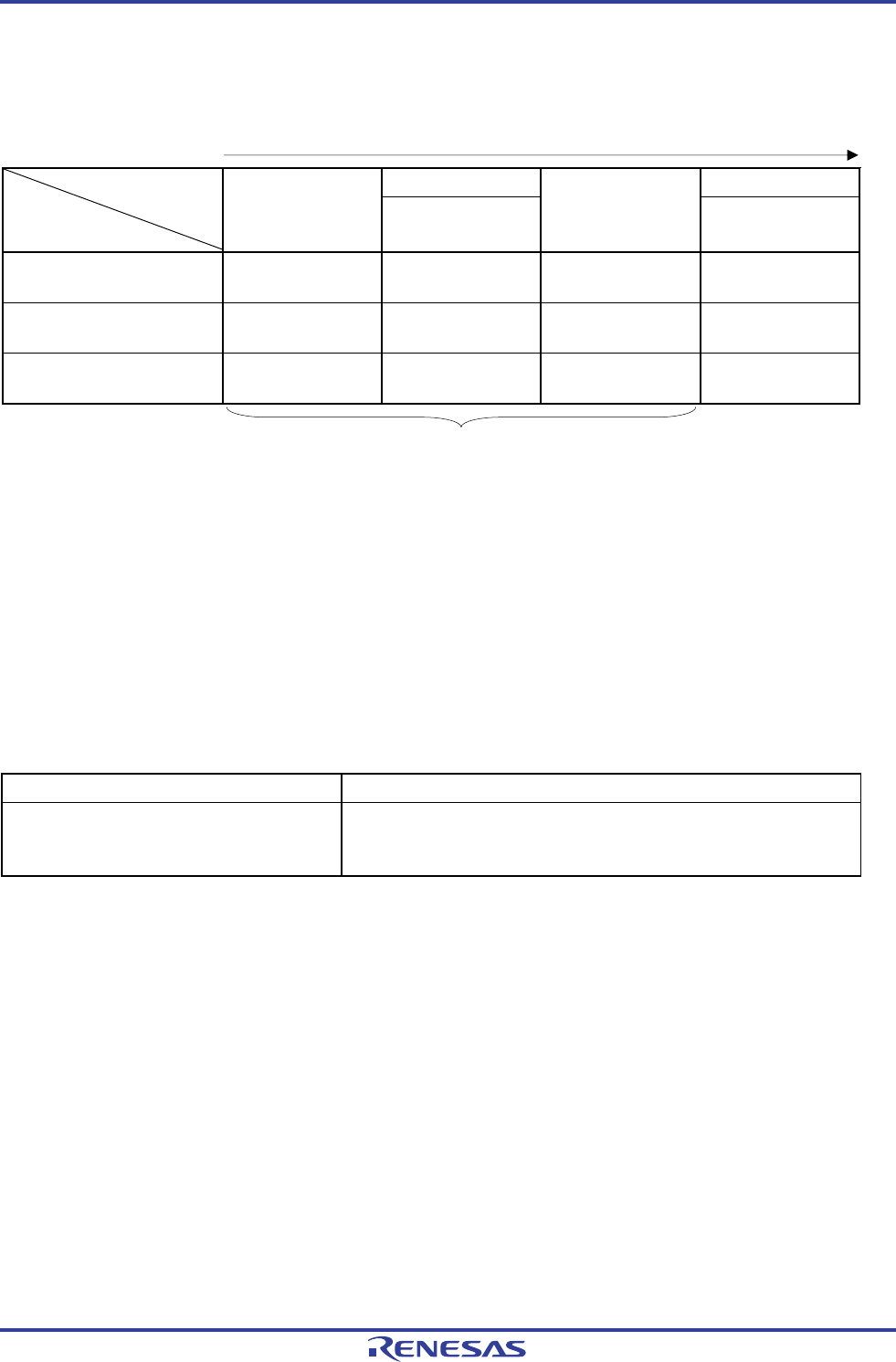
Table 5-3. CPU Clock Transition and SFR Register Setting Examples (4/5)
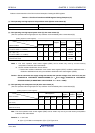
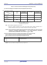
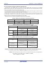
(9) CPU clock changing from subsystem clock (D) to high-speed system clock (C)
(Setting sequence of SFR registers)
CSC Register CKC Register
Setting Flag of SFR Register
Status Transition
OSTS
Register
MSTOP
OSTC Register
CSS
(D) → (C) (X1 clock: 1 MHz ≤
f
X ≤ 10 MHz)
Note 0 Must be checked 0
(D) → (C) (X1 clock: 10 MHz <
f
X ≤ 20 MHz)
Note 0 Must be checked 0
(D) → (C) (external main
clock)
Note 0 Must not be checked 0
Unnecessary if the CPU is operating
with the high-speed system clock
Note Set the oscillation stabilization time as follows.
• Desired the oscillation stabilization time counter status register (OSTC) oscillation stabilization time ≤
Oscillation stabilization time set by the oscillation stabilization time select register (OSTS)
Caution Set the clock after the supply voltage has reached the operable voltage of the clock to be set (see
CHAPTER 29 ELECTRICAL SPECIFICATIONS (TA = −40 to +85°C), CHAPTER 30 ELECTRICAL
SPECIFICATIONS (G: INDUSTRIAL APPLICATIONS T
A = −40 to + 105°C).
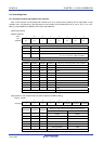
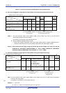
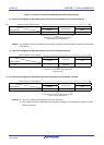
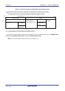
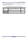
(10) • HALT mode (E) set while CPU is operating with high-speed on-chip oscillator clock (B)
• HALT mode (F) set while CPU is operating with high-speed system clock (C)
• HALT mode (G) set while CPU is operating with subsystem clock (D)
Status Transition Setting
(B) → (E)
(C) → (F)
(D) → (G)
Executing HALT instruction
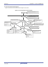
Remark (A) to (J) in Table 5-3 correspond to (A) to (J) in Figure 5-15.
<R>