


RL78/G1A CHAPTER 13 SERIAL INTERFACE IICA
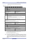
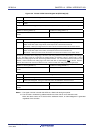
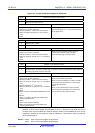
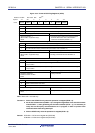
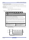
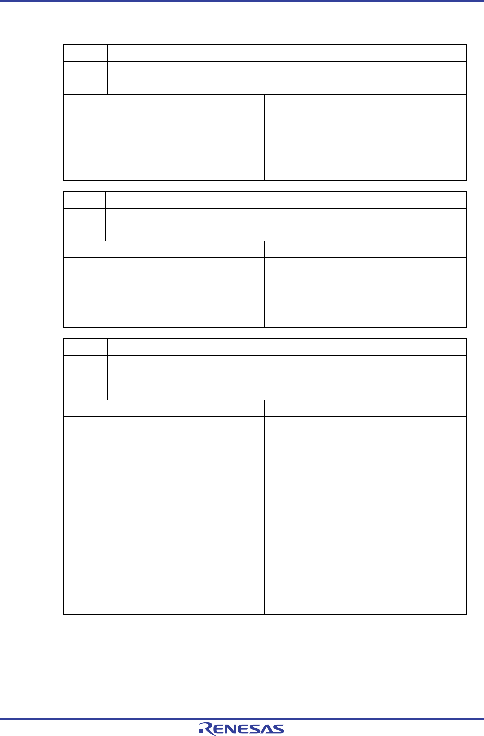
Figure 13-7. Format of IICA Status Register 0 (IICS0) (2/3)
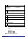
EXC0 Detection of extension code reception
0 Extension code was not received.
1 Extension code was received.
Condition for clearing (EXC0 = 0) Condition for setting (EXC0 = 1)
• When a start condition is detected
• When the higher four bits of the received address
data is either “0000” or “1111” (set at the rising edge
of the eighth clock).
• When a stop condition is detected
• Cleared by LREL0 = 1 (exit from communications)
• When the IICE0 bit changes from 1 to 0 (operation
stop)
• Reset
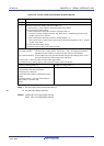
COI0 Detection of matching addresses
0 Addresses do not match.
1 Addresses match.
Condition for clearing (COI0 = 0) Condition for setting (COI0 = 1)
• When a start condition is detected
• When the received address matches the local
address (slave address register 0 (SVA0))
(set at the rising edge of the eighth clock).
• When a stop condition is detected
• Cleared by LREL0 = 1 (exit from communications)
• When the IICE0 bit changes from 1 to 0 (operation
stop)
• Reset
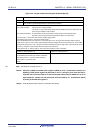
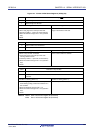
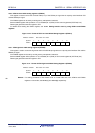
TRC0 Detection of transmit/receive status
0 Receive status (other than transmit status). The SDAA0 line is set for high impedance.
1 Transmit status. The value in the SO0 latch is enabled for output to the SDAA0 line (valid starting at
the falling edge of the first byte’s ninth clock).
Condition for clearing (TRC0 = 0) Condition for setting (TRC0 = 1)
<Both master and slave>
<Master>
• When a stop condition is detected
• When a start condition is generated
• Cleared by LREL0 = 1 (exit from communications)
• When 0 (master transmission) is output to the LSB
(transfer direction specification bit) of the first byte
(during address transfer)
• When the IICE0 bit changes from 1 to 0 (operation
stop)
• Cleared by WREL0 = 1
Note
(wait cancel)
<Slave>
• When the ALD0 bit changes from 0 to 1 (arbitration
loss)
• When 1 (slave transmission) is input to the LSB
(transfer direction specification bit) of the first byte
from the master (during address transfer)
• Reset
• When not used for communication (MSTS0, EXC0, COI0
= 0)
<Master>
• When “1” is output to the first byte’s LSB (transfer
direction specification bit)
<Slave>
• When a start condition is detected
• When “0” is input to the first byte’s LSB (transfer
direction specification bit)
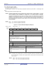
Note When bit 3 (TRC0) of the IICA status register 0 (IICS0) is set to 1 (transmission status), bit 5
(WREL0) of IICA control register 00 (IICCTL00) is set to 1 during the ninth clock and wait is
canceled, after which the TRC0 bit is cleared (reception status) and the SDAA0 line is set to high
impedance. Release the wait performed while the TRC0 bit is 1 (transmission status) by writing to
the IICA shift register 0.
Remark LREL0: Bit 6 of IICA control register 00 (IICCTL00)
IICE0: Bit 7 of IICA control register 00 (IICCTL00)
R01UH0305EJ0200 Rev.2.00 579
Jul 04, 2013