


RL78/G1A CHAPTER 13 SERIAL INTERFACE IICA
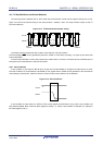
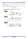
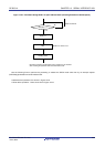
13.5.9 Address match detection method
In I
2
C bus mode, the master device can select a particular slave device by transmitting the corresponding slave address.
Address match can be detected automatically by hardware. An interrupt request (INTIICA0) occurs when the address
set to the slave address register 0 (SVA0) matches the slave address sent by the master device, or when an extension
code has been received.
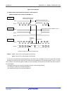
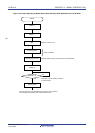
13.5.10 Error detection
In I
2
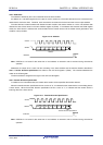
C bus mode, the status of the serial data bus (SDAA0) during data transmission is captured by the IICA shift
register 0 (IICA0) of the transmitting device, so the IICA data prior to transmission can be compared with the transmitted
IICA data to enable detection of transmission errors. A transmission error is judged as having occurred when the
compared data values do not match.
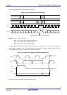
13.5.11 Extension code
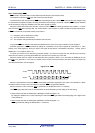
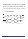
(1) When the higher 4 bits of the receive address are either “0000” or “1111”, the extension code reception flag (EXC0)
is set to 1 for extension code reception and an interrupt request (INTIICA0) is issued at the falling edge of the
eighth clock. The local address stored in the slave address register 0 (SVA0) is not affected.
(2) The settings below are specified if 11110xx0 is transferred from the master by using a 10-bit address transfer when
the SVA0 register is set to 11110xx0. Note that INTIICA0 occurs at the falling edge of the eighth clock.
• Higher four bits of data match: EXC0 = 1
• Seven bits of data match: COI0 = 1
Remark EXC0: Bit 5 of IICA status register 0 (IICS0)
COI0: Bit 4 of IICA status register 0 (IICS0)
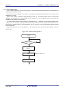
(3) Since the processing after the interrupt request occurs differs according to the data that follows the extension code,
such processing is performed by software.
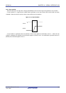
If the extension code is received while a slave device is operating, then the slave device is participating in
communication even if its address does not match.
For example, after the extension code is received, if you do not wish to operate the target device as a slave device,
set bit 6 (LREL0) of IICA control register 00 (IICCTL00) to 1 to set the standby mode for the next communication
operation.
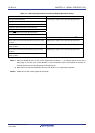
Table 13-3. Bit Definitions of Major Extension Codes
Slave Address R/W Bit Description
0 0 0 0 0 0 0 0 General call address
1 1 1 1 0 x x 0 10-bit slave address specification (during address
authentication)
1 1 1 1 0 x x 1 10-bit slave address specification (after address match, when
read command is issued)
Remark See the I
2
C bus specifications issued by NXP Semiconductors for details of extension codes other than those
described above.
R01UH0305EJ0200 Rev.2.00 598
Jul 04, 2013