


RL78/G1A CHAPTER 13 SERIAL INTERFACE IICA
13.5.15 Cautions
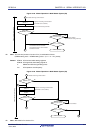
(1) When STCEN = 0
Immediately after I
2
C operation is enabled (IICE0 = 1), the bus communication status (IICBSY = 1) is recognized
regardless of the actual bus status. When changing from a mode in which no stop condition has been detected to a
master device communication mode, first generate a stop condition to release the bus, then perform master device
communication.
When using multiple masters, it is not possible to perform master device communication when the bus has not
been released (when a stop condition has not been detected).
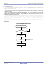
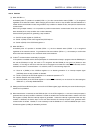
Use the following sequence for generating a stop condition.
<1> Set IICA control register 01 (IICCTL01).
<2> Set bit 7 (IICE0) of IICA control register 00 (IICCTL00) to 1.
<3> Set bit 0 (SPT0) of the IICCTL00 register to 1.
(2) When STCEN = 1
Immediately after I
2
C operation is enabled (IICE0 = 1), the bus released status (IICBSY = 0) is recognized
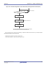
regardless of the actual bus status. To generate the first start condition (STT0 = 1), it is necessary to confirm that
the bus has been released, so as to not disturb other communications.
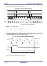
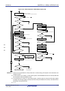
(3) If other I
2
C communications are already in progress
If I
2
C operation is enabled and the device participates in communication already in progress when the SDAA0 pin is
low and the SCLA0 pin is high, the macro of I
2
C recognizes that the SDAA0 pin has gone low (detects a start
condition). If the value on the bus at this time can be recognized as an extension code, ACK is returned, but this
interferes with other I
2
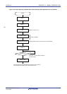
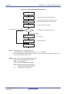
C communications. To avoid this, start I
2
C in the following sequence.
Jul 04, 2013
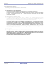
<1> Clear bit 4 (SPIE0) of the IICCTL00 register to 0 to disable generation of an interrupt request signal
(INTIICA0) when the stop condition is detected.
<2> Set bit 7 (IICE0) of the IICCTL00 register to 1 to enable the operation of I
2
C.
<3> Wait for detection of the start condition.
<4> Set bit 6 (LREL0) of the IICCTL00 register to 1 before ACK is returned (4 to 72 clocks of f
MCK after setting the
IICE0 bit to 1), to forcibly disable detection.
<R>
(4) Setting the STT0 and SPT0 bits (bits 1 and 0 of the IICCTL00 register) again after they are set and before they are
cleared to 0 is prohibited.
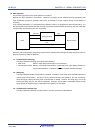
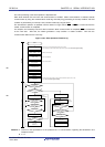
(5) When transmission is reserved, set the SPIE0 bit (bit 4 of the IICTL0 register) to 1 so that an interrupt request is
generated when the stop condition is detected. Transfer is started when communication data is written to the IICA
shift register 0 (IICA0) after the interrupt request is generated. Unless the interrupt is generated when the stop
condition is detected, the device stops in the wait state because the interrupt request is not generated when
communication is started. However, it is not necessary to set the SPIE0 bit to 1 when the MSTS0 bit (bit 7 of the
IICA status register 0 (IICS0)) is detected by software.
R01UH0305EJ0200 Rev.2.00 608