


RL78/G1A CHAPTER 16 INTERRUPT FUNCTIONS
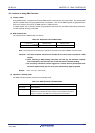
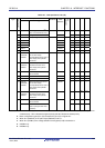
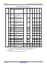
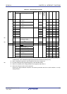
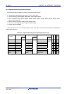
Table 16-1. Interrupt Source List (1/3)
Interrupt Source
Interrupt
Type
Default Priority
Note 1
Name Trigger
Internal/
External
Vector
Table
Address
Basic
Configuration
Type
Note 2
64-pin 48-pin 32-pin 25-pin
0 INTWDTI Watchdog timer interval
Note 3
(75% of overflow time+1/2fIL)
0004H √ √ √ √
1 INTLVI Voltage detection
Note 4
Internal
0006H
(A)
√ √ √ √
2 INTP0 0008H √ √ √ √
3 INTP1 000AH √ √ √ √
4 INTP2 000CH √ √ √ √
5 INTP3 000EH √ √ √ √
6 INTP4 0010H √ √ √ √
7 INTP5
Pin input edge detection External
0012H
(B)
√ √ − −
8 INTST2/
INTCSI20/
INTIIC20
UART2 transmission transfer
end or buffer empty
interrupt/CSI20 transfer end or
buffer empty interrupt
/IIC20
transfer end
0014H √ √ √ −
9 INTSR2/
INTCSI21/
INTIIC21
UART2 reception transfer
end/CSI21 transfer end or
buffer empty interrupt
/IIC21
transfer end
0016H √ √ √
Note 5
−
10 INTSRE2 UART2 reception communication
error occurrence
0018H √ √ √ −
11 INTDMA0 End of DMA0 transfer 001AH √ √ √ √
12 INTDMA1 End of DMA1 transfer 001CH √ √ √ √
13 INTST0/
INTCSI00/
INTIIC00
UART0 transmission transfer
end or buffer empty
interrupt/CSI00 transfer end or
buffer empty interrupt
/IIC00
transfer end
001EH √ √ √ √
14 INTSR0/
INTCSI01/
INTIIC01
UART0 reception transfer
end/CSI01 transfer end or
buffer empty interrupt
/IIC01
transfer end
0020H √ √ √
Note 6
√
Note 6
INTSRE0 UART0 reception communication
error occurrence
√ √ √ √
Maskable
15
INTTM01H End of timer channel 1 count or
capture (at higher 8-bit timer
operation)
Internal
0022H
(A)
√ √ √ √
Notes 1. The default priority determines the sequence of interrupts if two or more maskable interrupts occur
simultaneously. Zero indicates the highest priority and 39 indicates the lowest priority.
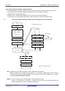
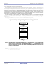
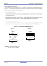
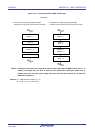
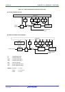
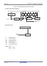
2. Basic configuration types (A) to (D) correspond to (A) to (D) in Figure 16-1.
3. When bit 7 (WDTINT) of the option byte (000C0H) is set to 1.
4. When bit 7 (LVIMD) of the voltage detection level register (LVIS) is cleared to 0.
5. INTSR2 only.
6. INTSR0 only.
R01UH0305EJ0200 Rev.2.00 689
Jul 04, 2013